v1.5.655 – 2025-11-26
Fix for Freq Analyser3 when changing FFT size
v1.5.654 – 2025-11-25
Renameable (but not auto-duplicate) pins can now be renamed correctly.
v1.5.652 – 2025-11-24
Freq Analyser3 – min and max dB pins now work correctly.
v1.5.651 – 2025-10-14
Fix for some soundfonts producing unwanted clicks during their looping stages.
v1.5.650 – 2025-10-13
Fix for MIDI automation not being sent in some cases.
v1.5.648 – 2025-09-26
SE now displays error when attempting to load .synthedit files as prefabs, .SE1 or .seprefab files load correctly as prefabs.
Note: SE1 files from V1.4 need V1.4 installed to migrate them to a V1.5 prefab structure.
Audio settings panel no longer attempts to sync the sample-rate dropdown with the ASIO driver settings.
v1.5.647 – 2025-09-23
Code Skeleton script now copies module to ‘modules-staged’ folder
The Build Code Skeleton operation is now placing mp_sdk_gui.cpp and mp_sdk_gui2.h into the sdk folder.
The Code Skeleton no longer writes useless headers.
v1.5.646 – 2025-09-22
The sample rate selector jumps back to current setting whilst you are trying to change it.
Fixed crashes when attempting to change preset on empty document.
MIDI-CV2 now has more accurate smoothing on the pitch-bender signal.
Added Blob Overloader (DSP) and Blob overloader (GUI) modules.
v1.5.645 – 2025-09-17
MIDI-CV2 Has more accurate smoothing on pitch-bender signal
v1.5.644 – 2025-09-15
fix for AU Validation of enum parametersFix Registration name not saving in Windows App Store build
v1.5.643 – 2025-08-21
Added command line arg ‘/upgradexml’ for use by SynthEdit 1.6 when loading older project files.
v1.5.642 – 2025-08-14
Audio settings sample-rate selection is now always enabled.
v1.5.640 – 2025-08-07
fix for effects on mono tracks in Logic Pro
v1.5.639 – 2025-07-24
Fix unwanted black areas when resizing windows (AT LAST!)
Dragging a module is now undoable.
v1.5.638 – 2025-07-17
Fix for misaligned CPU graphs on some modules.
Dragging a module is now undoable.
v1.5.636 – 2025-07-15
Fix for windows refreshing unnecessarily with deep-colour disabled
v1.5.634 – 2025-07-02
Fix for module browser opening squashed with ‘disable deep color’.
v1.5.633 – 2025-07-01
Update simdutf to latest version.
v1.5.632 – 2025-06-30
Experimental fix for module browser being too small.
v1.5.631 – 2025-06-26
Views now refresh their HDR mode when dragged to new monitor.
v1.5.630 – 2025-06-16
More consistent rendering of transparency (alpha) on 8-bit swapchains, and on HDR screens.
Added Gamma Test module and png
Added ‘Disable Deep Color Swapchain’ option for low-powered GPUs
v1.5.628 – 2025-05-14
[0154] Rotary Switch – mouse detection shifted left
v1.5.627 – 2025-05-12
Fix hang when properties pane (at right) is showing many changing parameters.
v1.5.626 – 2025-05-12
Fix hang when an ASIO driver fails to start.
Fix crash when switching ASIO drivers.
v1.5.625 – 2025-05-01
Fix for GCC compiler warnings
v1.5.624 – 2025-04-29
Fix VST3 plugins not recalling MIDI Automation
v1.5.623 – 2025-04-28
Improvements to ASIO driver setup.
Fix for audio driver setup repeatedly reverting to 11k sample rate.
ASIO – fixed some driver control panels failing to open from preferences dialog.
v1.5.622 – 2025-04-21
Fix hang when using audio driver “” (No audio driver selected)
v1.5.621 – 2025-04-14
Fix for audio engine crash when running with no sound-out module.
v1.5.620 – 2025-04-11
Fix “hang” sometimes when using ASIO control panel.
Also seems to have cured occasional/frequent sound engine crashes too.
Fix buzzing after disconnecting wires to Sound-Out module while audio is active.
Fix for SynthEdit running at the wrong sample rate when the ASIO driver doesn’t support the user preference.
v1.5.617 – 2025-04-08
[0147] Changing a pin in the properties panel causes Processor to restart
v1.5.616 – 2025-03-27
Fix export log’s erroneous “OTHER only” message
v1.5.614 – 2025-03-14
Faster font rendering.
Fix for sliders losing their Min/Max settings during un-containerize process.
v1.5.613 – 2025-03-06
Fix new modules getting placed at origin (0,0) (CenterPoint() function bug).
v1.5.612 – 2025-02-21
AU blank initial preset name now displays as ‘Default’ as in VST3 plugins
v1.5.611 – 2025-02-20
Fix for the Peak Det at 192kHz (instant attack like other rates)
VST3 – fix Processor and Editor values un-synced when DAW changes preset.
V1.5.610 – 2025-02-13
VST3 plugins ‘Save Preset’ now opens at the correct VST3 preset folder
VST3 plugins ‘Save Preset’ now fills in a suggested Preset filename (not just *.vstpreset)
VST3 – Saving and Overwriting a preset will now clear the ‘changed’ indicator (HC_PROGRAM_MODIFIED)
V1.5.609 – 2025-02-05
Various modules: – more robust initialization of lookup tables
V1.5.608 – 2025-02-04
JUCE export – correctly quotes resource file names in CMakeLists.txt
V1.5.606 – 2025-01-31
File Dialog modules now correctly shorten paths to Soundfonts etc. when they are in a sub-folder
Audio Files setting now applies to Soundfonts (as well as wavs).
V1.5.605 – 2025-01-31
Fix crash in Oscillator2 when the pitch goes infinite.
v1.5.602 – 2025-01-29
Export-JUCE now ensures that the target resources folder exists.
v1.5.601 – 2025-01-28
Fixed crashing on export-plugins. AppStore Build. (Missing licence.txt file)
v1.5.600 – 2025-01-27
Fixed crashing on export-plugins. (Missing licence.txt file)
v1.5.597 – 2025-01-23
Fix for SDK function ‘getRegisteredName()’ not working in plugins
v1.5.596 – 2025-01-23
More robust preset handling (with large presets)
v1.5.595 – 2025-01-21
#91 Debug display text-meter freezes.
v1.5.592 – 2025-01-09
Fix for low brightness on HDR monitors.
VST3 activating “Ignore Program Change” even when not enabled during export.
v1.5.589 – 2024-12-19
SynthEdit now retains MIDI device settings more robustly.
v1.5.588 – 2024-12-18
Inserting a prefab now respects the original z-order (front-to-back)
Improved fix for prefab top-level modules Z-order
v1.5.587 – 2024-12-16
Fixed “Don’t Export” option on module causing module to mute in Editor.
Added option “Disable Hardware Graphics” for intel GPUs [0081] Intel GPU perform poorly with SynthEdit
v1.5.586 – 2024-12-09
Inserting a prefab now respects the original z-order (front-to-back)
v1.5.585 – 2024-12-06
[0068] Fix for rounding error on integer parameters with negative values.
v1.5.584 – 2024-12-05
Toolbar preset list now shows empty preset names as e.g. “Patch 004″Toolbar Preset List now syncs with Preset Browsers in project
v1.5.583 – 2024-12-04
[0068] Better rounding of negative numbers when using integer parameters
v1.5.582 – 2024-12-03
‘Find’ dialog will now update the Properties pane when it finds a module
v1.5.581 – 2024-11-25
[0073] Some Characters are Excluded from Preset Names on Plugin Export
v1.5.580 – 2024-11-22
[0072] VST Plugins not saving MIDI Learn info in presets
v1.5.579 – 2024-11-21
[0067] Ableton Live params not updated on internal preset change.
v1.5.577 – 2024-11-08
More accurate CPU readout on modules that sleep often
v1.5.576 – 2024-10-30
Fixed crashing caused by modules with output pins having non-sequential IDs
v1.5.575 – 2024-10-24
SynthEdit downloaded from the Microsoft App Store now has the same assets as the regular version.
The installer now creates ‘modules-staged’ folder during installation.
Added additional mac_assets to App Store build
v1.5.573 – 2024-10-21
Pasting a module now updates the properties pane to reflect the pasted module.
Enable Microsoft Store features
v1.5.572 – 2024-10-11
Fix for generate-code-skeleton CMake with GUI modules.
Plugins will not crash when a GUI module attempts to send more than 5MB to Processor. The oversized message will be dropped.
v1.5.571 – 2024-10-08
Updated ‘Build Code Skeleton’ for tutorial
ProcessorStateMgr now applies Ignore-PC when storing presets
v1.5.570 – 2024-09-25
Fixed the message queue being restricted to 100kB (should be 5MB).
v1.5.569 – 2024-09-24
Improve font vertical alignment on macOS
Fix for recalling initial preset which uses Ignore-PC in Wavelab 12
v1.5.567 – 2024-09-18
[0053] VST3 plugin creates a preset called “Full Reset”
v1.5.566 – 2024-09-16
Random2 module replaces Random Voltage. Random2 is truly random, (except in offline mode where it is consistently ‘random’)
v1.5.565 – 2024-09-12
Improved syncing of presets between plugins and DAW
v1.5.564 – 2024-09-09
Fixed crash when Scope tries to send data *to* DSP
v1.5.563 – 2024-09-02
[0036] Fix for “wires don’t follow container resizing”.
v1.5.562 – 2024-08-28
[0025] When a module has captured the mouse, the ‘hover’ functionality is now restricted to only the module that captured the mouse.
v1.5.561 – 2024-08-28
Fix for Container plugs default value loading as “0” when it was saved as blank.
v1.5.560 – 2024-08-28
New warning if module writer forgot to specify “graphicsApi”fix warning on MIDI in module.
Fix possible crash in ListBoxImport Bank: now refreshes the current preset if it has changes Export Bank now includes tweaks to current presetInfo.
v1.5.559 – 2024-08-21
Fixed the installer sometimes not installing ‘VC Redist’.
VST3 plugins now save changes to the presets in Ableton Live when the Audio Engine is off.
v1.5.557 – 2024-08-21
No ‘failed to copy protect SEM’ messages when the SEM didn’t exist.
Fix for plugins not saving their latest state in Logic Pro X while the Processor is suspended.
v1.5.556 – 2024-08-14
Hide “Analyze Cancellation” :from menu
v1.5.553 – 2024-08-09
Fix for MIDI Learn not saving in DAW sessions
v1.5.552 – 2024-08-08
Fix for stuck notes in a MIDI-CV2 module when it’s “upstream” of another MIDI-CV2 module
v1.5.550 – 2024-08-06
Fix for the GUI turning dark after initial draw on macOS Sequoia
v1.5.549 – 2024-07-30
Improved mouse behaviour with connections.
Faster visual feedback after making a connection.
v1.5.548 – 2024-07-30
More sensible default window size when you have multiple screens.
MIDI-CV2 now respects MIDI Channel settings.
v1.5.544 – 2024-07-11
Fix for ‘Latency Timeshift’ module not working in plugins.
v1.5.543 – 2024-07-03
Fix for mouse hover (over resize adorners)
v1.5.542 – 2024-07-02
Fix for hover detection when mouse is already captured
v1.5.540 – 2024-07-02
Improvement for parameter automation in Apple Logic Pro
v1.5.539 – 2024-06-19
MPE Pressure and Brightness values now apply to voices after note-off.
v1.5.537 – 2024-06-13
Fix for VST3 UI not respecting ‘Ignore Program Change’
v1.5.535 – 2024-06-12
Pass the parameter /nowindowlimit to synthedit when launching to disable the 5 window limit
Default values on DSP BLOB pins now working (base64 encoded).
v1.5.534 – 2024-05-31
Added ‘ContextMenuHelper’ to make handing right-click menus easier.” (originally intended for SE1.6).
Added ‘ContextMenuHelper’ to make handing right-click menus easier.
v1.5.533 – 2024-05-22
Improved fix for Logic Pro automation bug
v1.5.532 – 2024-05-21
Fix for GUI not moving in response to automation in Logic Pro (ARM)
v1.5.531 – 2024-05-16
Fix for a potential crash when placing MIDI-CV2 into empty container
v1.5.529 – 2024-05-13
Better preset behaviour
v1.5.527 – 2024-05-02
SE2JUCE export – sessions. Presets now not written to disk (go in binary)
v1.5.526 – 2024-04-23
Fix for the oversampler module reporting incorrect CPU
v1.5.525 – 2024-04-17
Slider output is more accurate at end of smoothing.
v1.5.524 – 2024-04-16
Sample Osc2 (SF2) module now supports independent left/right loop points.
v1.5.523 – 2024-04-16
Lower CPU on macOS (-ffast-math)
Improved trimming of skin filenames when browsing via properties pane
v1.5.521 – 2024-03-26
Fix for SEMs not being copied to VST3 because of anti-virus software due to copy-protect step.
Fix ‘missing OversamplingDetect.sem’ message
v1.5.520 – 2024-03-22
Modules with no pins can now be selected/dragged.
Modules with no DSP pins are now instantiated anyhow in plugin
Structure Group: easier to select lines inside a structure group
‘Exclude from plugin’ no longer mutes module within editor
v1.5.519 – 2024-03-21
Container GUI Input pins now propagate a default value inside to the connected module.
v1.5.518 – 2024-03-20
Fix sub-panels getting stuck in ‘Visible’ mode when the container has defaults set on unconnected GUI input pins.
v1.5.517 – 2024-03-20
Freq-Analyser – nicer clipping at right axis
v1.5.516 – 2024-03-18
Fix for jittery controls on AU plugins.
v1.5.515 – 2024-03-15
Structure-Group no longer leaves ‘trails’ when dragged.
v1.5.514 – 2024-03-14
Fix for flickering graphics on low-end GPUs.
v1.5.513 – 2024-03-13
Fixed BPM-Tempo module not sleeping.
v1.5.512 – 2024-03-06
Fix for latency reporting on AU
v1.5.511 – 2024-03-04
AUs now report latency to DAW
v1.5.510 – 2024-02-28
Fixed the crash when Replace dialog indirectly closes the Window that opened it.
v1.5.507 – 2024-02-26
Export as JUCE no longer erases VST3 plugin.
Export VST now exports only the relevant skin files.
v1.5.506 – 2024-02-22
Better MIDI 2.0 handling
v1.5.504 – 2024-02-21
Support for IMpGraphics3::hitTest2new module: Diagnostic/Bad Voltage
Menu “Show skin files” now always enabled.
Export-juce reminds to save changes if necessary.
Better decoding of MIDI messages (ignore 16 byte)
SV Filter2 more robust in the face of NaNs.
Fix for jittering controls in Ableton Live 11 VST3s on mac.
v1.5.503 – 2024-02-05
Fix for AU parameter automation not working
v1.5.502 – 2024-02-02
Hover working again.
v1.5.499 – 2024-01-31
Export JUCE now support adding manual Binary Resources to the JUCE project
v1.5.498 – 2024-01-31
No ‘Save Changes’ msg when exporting as JUCE
v1.5.497 – 2024-01-29
More robust ProtectedFile2
Fix for Frequency Analyzer 2
Better description of skin files in the readme.txt
Waveshaper formula now updates when changes made from Properties panel
VA Moog Filter is a little more stable at high frequency settings
v1.5.496 – 2024-01-26
Fix for crash with FeedbackDelay – MIDI
v1.5.495 – 2024-01-26
Fixed crash in host.resolveFilename()
v1.5.494 – 2024-01-25
Oversampling Control defaults to ‘off’
v1.5.493 – 2024-01-24
Support for larger clipping area.
Fix host-control “Oversampling/Rate” when accessed from DSP.
v1.5.492 – 2024-01-19
Resolve Filename look in plugin Resources folder by default (not x86_64 folder)
v1.5.490 – 2024-01-12
Re-optimized SINC filters
Fix incorrect behaviour when DAW buffer size not multiple of 4 (SSE prequel)
v1.5.488 – 2024-01-11
Revert bug in Pan module
SDK – fix possible crash in Bitmap.GetSizeF()
v1.5.487 – 2024-01-10
Fix for the SINC filter over-writing the output buffer.
v1.5.486 – 2024-01-10
Lower CPU spikes when restarting plugin (e.g. due to patch cables or oversampling)
v1.5.485 – 2024-01-10
Fix possible status error in Pan module.
Attempt to fix preset-change glitches in plugins with patch-cables.
v1.5.484 – 2024-01-09
Fix for Scope text drawing upside down on macOS
v1.5.483 – 2024-01-08
Additional fix for high CPU when switching presets
v1.5.482 – 2024-01-05
SFZ files now load on background thread
v1.5.481 – 2024-01-04
New module” Fixed Values (int64)
Fix for entering 64-bit integers in properties pane
Better support for auto duplicating GUI pins (GUI fixed values modules).
v1.5.479 – 2024-01-03
Fix for excessive CPU when switching presets (empty PM BLOB comparison)
v1.5.477 – 2024-01-02
Build-Code-Skeleton – Better CMake generation.
v1.5.476 – 2023-12-23
Panels open a little faster. (cached paramID).
v1.5.475 – 2023-12-22
New Fixed-Values-GUI modules.
v1.5.474 – 2023-12-21
Fix to avoid resetting controls when containerizing things.
v1.5.473 – 2023-12-21
Fix glitchy node insertion on lines.
Fix for arrow on curvy lines being off center
v1.5.472 – 2023-12-20
Better support for 64-bit integers.
Better pin names when Containerizing.
v1.5.471 – 2023-12-14
Smarter containerize procedure, (minimizes the number of plugs).
v1.5.470 – 2023-12-13
Update for JUCE export.
v1.5.469 – 2023-12-12
Fix for JUCE export when skin filenames contains spaces.
v1.5.468 – 2023-12-08
Better reporting of multi-midi-cv errors.
v1.5.466 – 2023-12-07
Fix possible crash when deleting a module with it’s debug screen open.
v1.5.465 – 2023-12-05
Fixed duplicated wires when Containerizing.
v1.5.464 – 2023-12-04
Fix for MPE on MIDI chan 16.
v1.5.463 – 2023-11-29
Fix for voice allocation bug (over-stealing)
v1.5.462 – 2023-11-29
More efficient caching of graphics resources (module outlines)
v1.5.461 – 2023-11-28
GUI Keyboard – less visually stuck notes
Arpeggiator – less stuck notes
v1.5.460 – 2023-11-28
Fix crash when AU fails to load a SEM.
Better behaviour when running under Parallels emulator on M1.
v1.5.459 – 2023-11-23
Fix tooltips not working on AU
v1.5.458 – 2023-11-23
Added support for AU ‘Reset’ feature (clear the effect ‘tail’)
v1.5.457 – 2023-11-23
Fix crash when BLOB size exceeds message queue capacity.
v1.5.456 – 2023-11-20
Fix Text Entry position in AU.
v1.5.455 – 2023-11-17
“Lasso” selection ignores hidden sub-panels.
v1.5.454 – 2023-11-15
Better thread-safety when accessing presets
v1.5.453 – 2023-11-14
More consistent line-spacing on AU text
v1.5.452 – 2023-11-14
Fix for text alignment issues in Logic Pro and Garage Band
v1.5.451 – 2023-11-01
Fix for partially blank GUI in FL Studio
v1.5.450 – 2023-11-01
Fix for presets not affecting DSP in Prosonus .
Keyboard (CV) responding to clicks in plugin.
v1.5.449 – 2023-10-31
Fixed MIDI timing on AU.
Joystick image clips it’s drawing.
v1.5.448 – 2023-10-31
Optimized drawing on macOS
v1.5.447 – 2023-10-30
Fix possible crash with feedback delay modules.
CPU Meter clips to it’s bounds.
v1.5.446 – 2023-10-24
Fix all text italic.
Fix bitmap brush offset.
v1.5.445 – 2023-10-24
Bitmap brush drawing at correct phase.
v1.5.444 – 2023-10-23
Better color blending on macOS.
Impulse Response now updates it’s axis labels when sample-rate changes.
‘Duplicate modules’ message from SEM bundles when scanning VSTs.
v1.5.442 – 2023-10-16
SFZ Sample player now includes mac version.
v1.5.441 – 2023-10-13
SFZ Player now auto-reloads SFZ file anytime the file is updated.
v1.5.440 – 2023-10-13
Changing Patch Mem-Integers range now reflected in MIDI learn range.
v1.5.439 – 2023-09-28
Fix for crash when mousing over panel background after rescanning modules
v1.5.438 – 2023-09-28
Fix for not scanning some mac modules
v1.5.437 – 2023-09-20
Fix for Logic Pro crash (arcs)
v1.5.436 – 2023-09-19
Fix crash in Logic Pro when drawing invalid arc segments
v1.5.435 – 2023-09-15
VST3 better support for poly-aftertouch (in the absence of Note-on events).
Midi Player2 – new pin “Send Clocks” allows you to disable sending of MIDI Clock messages.
MIDI learn working on List parameters.
Added support for universal SEM bundles.
v1.5.434 – 2023-09-14
Freq Analyser – Fixed Hz labeling.
v1.5.433 – 2023-09-04
Fix for non-English number formatting etc. (locale).
v1.5.432 – 2023-09-01
MIDI converter now respects poly pressure channel.
MIDI Monitor now shows PolyAfterTouch as ‘PolyAfterTouch’ (not ‘AfterTouch’).
v1.5.431 – 2023-09-01
MIDI conversion now correct for poly aftertouch with value of zero.
v1.5.430 – 2023-09-01
Fix project loading and exporting when Windows username contains non-western characters.
v1.5.429 – 2023-08-31
Fix Increment3 ‘flashing’ (mouse grab feedback loop).
v1.5.427 – 2023-08-30
Fix for Increment module pulsing.
v1.5.426 – 2023-08-30
Better pin indexing on XML project export.
Better error reporting when exporting plugins.
v1.5.425 – 2023-08-29
MIDI Filter – now filters Poly aftertouch by key number.
v1.5.424 – 2023-08-28
When plugin is on track with fewer channels than the plugin has, extra output channels are ignored (were outputting to channel 0)
v1.5.423 – 2023-08-21
MIDI Switches now send all-notes-off when switching
v1.5.422 – 2023-08-18
New MIDI switch modules
v1.5.421 – 2023-08-18
Re-balanced voice stealing algorithm to give more importance to note duration
v1.5.420 – 2023-08-17
New module – Arpeggiator
v1.5.418 – 2023-08-17
Module browser scroll bar length is now proportionate to scrollable area.
The MIDI de-channelizer is back (adapted for MIDI 2.0).
MIDI Monitor is now clearer about note key vs note pitch.
v1.5.417 – 2023-08-11
Save-as-Plugins – avoids resetting the plugin identifier unless it’s blank.
v1.5.416 – 2023-08-11
VST3 – support for any number of surround channels up to 24, plus 36, 49, 64
v1.5.415 – 2023-08-11
VST3 – Added support for Surround channels of: 9-14, and 24 channels
The Module Browser now has scroll bar.
v1.5.414 – 2023-08-10
Removed ‘save fxb bank’ option. It only crashed 64-bit plugins.
v1.5.413 – 2023-08-10
Fix for VST3 surround plugins
v1.5.412 – 2023-08-09
Better support for surround formats in Cubase:
mono, stereo, quad, 5.0, 5.1, 7.0, 7.1
v1.5.411 – 2023-08-09
Fix for glitchy tooltips in MixBus
v1.5.410 – 2023-08-08
Fix Cubase reverb tails (silence flags)
v1.5.409 – 2023-08-07
Rack flag saving in XML project files
More robust filters (Butterworth V2)
v1.5.408 – 2023-08-04
Fix for Studio One – ‘plugin deactivated deactivated because it produced invalid data’
v1.5.407 – 2023-08-03
Projects without explicit patch-manager crashing in DAW (regression).
Fix for loading XML projects which were upgraded by SE 1.4.
v1.5.406 – 2023-07-21
Better snapping to grid when containerizing.
Patch Point modules not saving in SEM cache.
v1.5.405 – 2023-07-20
MIDI-In MPE mode now passes all Controllers on the Master Channel/s.
v1.5.404 – 2023-07-18
Fix for voices suspending too soon in some situations.
v1.5.403 – 2023-07-17
Fix crashes when copying/pasting
v1.5.402 – 2023-07-14
Connectors aligned better with plugs on structure view.
Module Browser – better grouping of filter results by category.
Dropping a new module snaps it to the grid.
v1.5.401 – 2023-07-14
Moved MPE Control module to category ‘MIDI’.
Fix for MPE-Mode not working when exporting instruments with no explicit patch-manager.
v1.5.400 – 2023-07-12
Fix for bitmap brush offset on macOS.
v1.5.399 – 2023-07-11
Fix for offset background in Reaper mac
v1.5.398 – 2023-07-07
Added export option ‘Create a VST2 using SE 1.4’
v1.5.397 – 2023-07-06
MIDI Out crashing when fed MIDI 2.0.
v1.5.396 – 2023-07-06
Module-browser – fix glitchy highlighting.
Tooltips not working in Harrisons MixBus (DAW).
v1.5.394 – 2023-06-30
Scroll wheel working on macOS.
Added Thick Osc source.
v1.5.393 – 2023-06-28
Butterworth Filters (V2) can now be set to a lower frequency (0.00001 * SR)
v1.5.392 – 2023-06-23
Polyphony Control working when in main container
v1.5.391 – 2023-06-23
Fix crash when MIDI-CV in main container
v1.5.390 – 2023-06-23
Listbox now responds to scroll wheel (or <ALT> Scroll wheel in editor).
v1.5.389 – 2023-06-23
BPM Tempo – new pin ‘Processor Resumed’ which is for clearing Reverb and Delay tails after the DAW has suspended the plugin for a while.
v1.5.387 – 2023-06-20
Overbright pixels now supported on macOS
Additive bitmaps now use sRGB color space (was RGB).
v1.5.386 – 2023-06-16
Reverb – kill reverb tail when looping a clip especially in FL Studio Clip Effects
v1.5.385 – 2023-06-16
Fix possible overload of DSP->GUI queue.
Butterworth Filters2 – changes to cutoff frequency are now smoother.
v1.5.384 – 2023-06-15
Fix updates from DSP -> GUI getting lost.
Fix for loading prefabs from the File menu.
v1.5.382 – 2023-06-14
Fix for containerizing a Slider might reset it to default values.
v1.5.381 – 2023-06-14
Remove “Remove Rack Module” context menu.
v1.5.380 – 2023-06-09
Fix for crash on mac (non-invertible transforms)
v1.5.379 – 2023-06-0
Tentative fix for Apple Silicon Logic Pro automation
v1.5.378 – 2023-06-09
Fix for crash on macOS (UTF conversion)
v1.5.377 – 2023-06-07
CI Added ‘DrawTextW’ variation which takes a ‘DrawTextOptions’ enumeration.
v1.5.376 – 2023-06-07
Fix for Find and Replace modules causing crashing.
v1.5.375 – 2023-06-01
Fix assertion on exit.
v1.5.374 – 2023-06-01
Scanning modules now shows ‘busy’ cursor.
Fix for occasional crashes in the Module Browser.
v1.5.373 – 2023-05-29
Fix for crash when drawing patch cables on macOS.
Module browser – color coded module names
v1.5.372 – 2023-05-25
List Box now scrolls to the current selection when updated programmatically.
Fix for objects ignoring mouse when made ‘visible’ directly under the mouse cursor.
v1.5.371 – 2023-05-24
Only one “Sound Engine is not responding” message (not two).
v1.5.370 – 2023-05-23
Attempted fix for objects getting shifted far off edges of panel
Unreleased
BLOB2 support
v1.5.368 – 2023-05-18
Fix for weirdness when opening a window with <CTRL> held
<ctrl> p – opens Preferences
v1.5.367 – 2023-05-17
Fix for crashes when adding new modules from the browser.
‘Save As’ dialog defaults to same folder that the project was loaded from.
v1.5.366 – 2023-05-11
Added ‘Rescan Modules’ menu. <ALT> E R
v1.5.365 – 2023-05-10
Fix crash when using the CPU Meter module in a plugin.
Faster loading time for VST plugins.
Added support for MIDI Poly/Mono channel mode messages (CC 126, 127)
v1.5.362 – 2023-05-05
Smart audio pin updated to double precision (for consistency in unit tests)
Fix spurious DSP restart.
MIDI 2.0 Bender working.
v1.5.361 – 2023-05-04
MIDI Bender Range support
v1.5.360 – 2023-05-04
Bender not working.
v1.5.358 – 2023-05-03
Smaller GMPI events.
v1.5.357 – 2023-05-03
Stricter enforcement of Manufacturer Code rules during export.
v1.5.356 – 2023-05-01
GMPI text (UTF8) pins now support file browser in properties panel.
v1.5.354 – 2023-04-24
Fix for Prefabs not scanning correctly.
v1.5.353 – 2023-04-19
Fixed scanning the wrong folder for modules.
v1.5.352 – 2023-04-18
Added mp3, ogg and flac file-extensions to dialog when opening Audio files.
v1.5.350 – 2023-04-13
File Dialog better at choosing starting folder.
v1.5.349 – 2023-03-31
Module Browser now groups module list by category
v1.5.348 – 2023-03-30
New module added – ‘MIDI Recorder’
v1.5.347 – 2023-03-29
Don’t export “Debugger” to WV.
XML Slider ‘hint’ not saving.
v1.5.346 – 2023-03-22
Latency compensation for MIDI signals.
Fix faulty file loading (.synthedit).
Fix XML patch format (repeat count).
Volt-to-Float2 now faster at converting ‘static’ signals.
Fix mono mode (MIDI CV2)Comparator Status errors.
v1.5.345 – 2023-03-15
Fix for some tests broken by recent updates.
v1.5.344 – 2023-03-14
New module ‘Silence Gate’ shuts off very quiet signals which are annoyingly streaming.
Faster async restarts in offline mode.
Fix delayed notes when played note count exceeds polyphony.
v1.5.343 – 2023-03-09
Fix for unresponsive mouse (when sub-panel hidden by click on child).
Better support for MIDI ‘Reset All Controllers’.
v1.5.342 – 2023-03-06
Module browser won’t collapse childrenadded operator= for DSP string pins and std::stringEnable MIDI 2.0 in AU plugins.
v1.5.341 – 2023-03-02
Fix for Butterworth filters not sleeping.
v1.5.340 – 2023-02-24
Fix for crashes when upgrading an old project.
v1.5.338 – 2023-02-20
Module browser group filter buggy.
v1.5.337 – 2023-02-20
Fix for MIDI Learn not working
v1.5.336 – 2023-02-16
Renaming a plug now reflects on the module immediately.
v1.5.335 – 2023-02-15
Fix inconsistent offline renders.
Fix for note-on on first sample of offline render.
v1.5.334 – 2023-02-13
Fix possible crash when clicking a bitmap that didn’t load.
Fix crashes when module .dll failed to load.
v1.5.333 – 2023-02-10
Disable cancellation testing code.
v1.5.332 – 2023-02-09
Spurious “Can’t load Module:” messages when save-as-vst.
Improved voice allocation, especially at the start of offline rendering.
v1.5.331 – 2023-02-02
Fix memory leak in plugins
v1.5.330 – 2023-02-01
Added ‘All Files’ option to load preset dialog.
Patchmem in/out now updates correct preset (not always #0).
v1.5.329 – 2023-02-01
New prefab ‘Pitch Bender’.
New module ‘Spring3’ – differentiates between mouse holding control and DAW holding it.
Improved support of oversampling and polyphony in different containers.
Fix for Spring 3 sticking.
v1.5.328 – 2023-01-31
New modules GUI Converters for Double and Int64.
New modules: ‘Float to Double’, ‘Double to Float’, ‘Int to Int64’ and ‘Int64 to Int’.
Auto scroll works with selection drag box.
Find and replace dialog, correct text color.
v1.5.327 – 2023-01-30
Fix possible crash when closing SE.
Fix crash when synth did not contain own patch-Automator
Attempt fix for patch – Automator downstream of oversampler (containing controls)
Altered module browser divider “Show on Module” working
v1.5.326 – 2023-01-25
Less laggy module browser (part 2).
v1.5.325 – 2023-01-23
Module Browser less slow.
v1.5.324 – 2023-01-23
New module ‘Float to MIDI’ – like MIDI-to-CC but also supports Bender and Mono Aftertouch.
v1.5.323 – 2023-01-20
Fix spurious “different version of some modules message” when plug defaults are changed from “” to “0”
v1.5.322 – 2023-01-20
Fewer memory leaks on macOS.
Fix for Freq Analyser crash
v1..5.321 – 2023-01-19
Fewer memory leaks in AU.
Fewer memory leaks.
Fix leaking Bitmaps in AU plugins.
v1.5.320 – 2023-01-17
Objects pasted in a structure go to the center of panel.
Helper methods for opening embedded files easily.
GUI SDK now has simplified resource finding.
v1.5.319 – 2023-01-16
Better support for SVG files
v1.5.318 – 2023-01-16
Scanning modules now updates module groups.
Fix HC_PROCESS_RENDERMODE.
Fix for ‘Sound In’ connections confused after migration from 1.4 project
Don’t save .synthedit files to most-recent-file list.
Module browser better highlighting of text under mouse.
v1.5.317 – 2023-01-11
Removed VST folder setting.
Fix silence flags when plugin has more than one set of outputs.
v1.5.316 – 2023-01-11
Fix for AU background image mis-aligned.
Bitmapbrush translation working on macOS.
v1.5.315 – 2023-01-09
Dragging module to a non child window no longer drops the module.
Clicking over module browser (while dragging) cancels module drag.
v1.5.314 – 2023-01-05
Fix for automatic converter modules not working in plugins.
v1.5.313 – 2023-01-03
Wave Recorder module now working in plugin.
Wave Player now working in plugins.
v1.5.312 – 2022-12-29
Skin text files can now contain comments (start line with ;).
Fix for sharing violation when upgrading a prefab.
v1.5.311 – 2022-12-28
Dragging a patch cable to an existing destination no longer draws two patch cables
<Ctrl> and <Shift> allow you to run a new patch-cable, without dragging an existing one.
v1.5.310 – 2022-12-27
Double-click opens container only if you didn’t click over an embedded control crashing switches.
v1.5.309 – 2022-12-27
Line nodes now respect snap-to-grid.
Fix for crash in save-as dialogue.
v1.5.308 – 2022-12-27
Fix for Windows not redrawing.
v1.5.307 – 2022-12-27
Bitmap fast-hit-test cleared when loading new bitmap.
Moved PkgInfo file into ‘Contents’.
DrawingFrame.open more robust.
v1.5.306 – 2022-12-26
Fix for spurious “module will be upgraded” dialogs.
Plugins now look for files (wav etc.) in plugins Resource folder.
Add ‘busy’ cursor when loading/saving projects.
v1.5.305 – 2022-12-23
Modules now slightly transparent to aid tracing wires.
v1.5.302 – 2022-12-22
Fix preset format (when parameter is polyphonic).
v1.5.301 – 2022-12-21
Fix possible crashes with SDK modules (pinIterator).
Fix possible crashes when loading older .synthedit projects.
v1.5.299 – 2022-12-21
Fix for messed up graphics (XML project format bug).
v1.5.297 – 2022-12-16
Fix loading XML projects with incomplete module database flags. (IO_CONTAINER_PLUG, IO_SETABLE_OUTPUT).
Fix for ‘CF_OLD_STYLE_LISTINTERFACE’ not stored in XML projects.
Fix ‘IO_SETABLE_OUTPUT’ not stored in XML projects.
Clean up confusion between pin id and pin idx.
Fixes for loading .synthedit project files (IO_SETABLE_OUTPUT).
v1.5.295 – 2022-12-14
Fix for module browser resize glitch.
Better behaviour when making new connections (temporary line hangs around longer).
v1.5.293 – 2022-12-13
Zoom relative to mouse position
v1.5.292 – 2022-12-13
Fix crash with ‘MIDI In’ but not ‘Sound Out’
v1.5.291 – 2022-12-13
MIDI IN – changed MPE Mode default to ‘off’.
Fix registration module not working in plugin.
Fix MIDI automation output.
v1.5.288 – 2022-12-12
Fix brightness issue with Plain Image module (in tile mode).
v1.5.287 – 2022-12-09
Export JUCE will now export to ../SE_Project/Resources/ (provided the synthedit project is also in a folder called ‘SE_Project’). Otherwise export to Documents/SynthEdit Projects/JUCE_Export/
v1.5.286 – 2022-12-09
Fix truncated CPU readout on debug panel.
Added new ‘Waveshaper2b GUI’ Sub-Control.
v1.5.285 – 2022-12-08
Fix for stuck notes in Cubase (multiple hits with hold-pedal).
Fix possible crash loading plugin (preset index error).
<ESC> now cancels cable dragging.
v1.5.284 – 2022-12-07
Fix for spurious feedback path warning.
Waveshaper2B now updates the text right after you type it.
v1.5.283 – 2022-12-05
Fix weirdness when upgrading modules on load
v1.5.282 – 2022-12-02
New smoothed Butterworth filters.
Fix possible crash when loading modules with fewer pins than when saved.
v1.5.280 – 2022-12-02
Fix unwanted latency with multiple patch-automators (upstream flag escaping local patch-automator).
MIDI Monitor now shows tuning changes correctly.
v1.5.278 – 2022-12-01
Fix Frequency Analyser crashing sometimes.
Fix wrong preset playing after ‘power on’.
v1.5.275 – 2022-11-25
MIDI Keyboard now sends MIDI 2.0
Module Browser has better resizing.
Module Browser – more conventional scrolling limits.
Browser – ‘All’ shows Container and IO Mod.
v1.5.273 – 2022-11-24
Fix tempo not initialized on DSP restart.
Fix for audio not responding to preset changes in some cases.
v1.5.272 – 2022-11-23
Hold <ALT> to Scroll Slider value in Editor (avoids accidentally scrolling it when navigating).
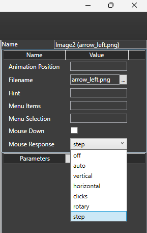
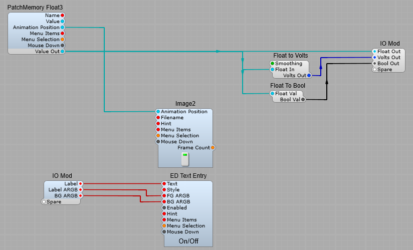
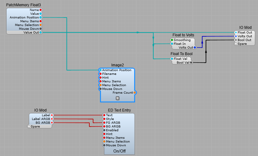
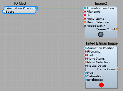
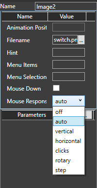
Mouse wheel now works on Image2.
Fix ‘Sound Out” module getting connections mixed up when upgrading from SE 1.4.
v1.5.271 – 2022-11-23
SE2JUCE now automatically adds resources to cmake.
v1.5.269 – 2022-11-16
Reverted latest vc_redist because it doesn’t work on azure pipelines yet.
v1.5.268 – 2022-11-15
SE now accepts command line switches ‘rego’ and ‘regoname’.
v1.5.266 – 2022-11-11
Fix crash on ASIO control panel.
v1.5.265 – 2022-11-11
Fix for Japanese preset names on macOS.
v1.5.264 – 2022-11-10
Updated to latest VC Redistributable (14.34.31931)
v1.5.263 – 2022-11-09
Popup Menu no longer ticks items in ‘momentary’ mode.
List-Combiner works better in ‘momentary’ mode.
v1.5.262 – 2022-11-04
Fix crashes (due to ‘repeat’ count wrong on patch mem).
v1.5.261 – 2022-11-04
Modules browser – scrolling resets whenever a new category is selected
Module Browser now uses triangles for expand/contract, the same as SE 1.4MB – colors closer to SE 1.4.
v1.5.258 – 2022-11-03
Fix for possible crash when loading a project (invalidate measure)
v1.5.257 – 2022-11-02
Module Browser – better scroll limits.
Module Browser resizes swapchain when app window resized.
v1.5.256 – 2022-11-02
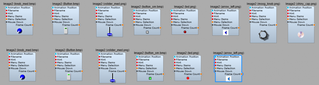
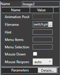
Better resizing of Image2 module when loading new image (in SynthEdit only).
v1.5.255 – 2022-11-02
Fix for tool-tips
Fix for crash when loading prefabs with obsolete modules.
Fix HC_POLYPHONY not avail in some plugins (with patch-manager in main container only).
Module Browser works all the way down.
Module Browser – <esc> cancels drag.
v1.5.254 – 2022-10-31
Fix mac plugin names converting to Camel-case text.
v1.5.253 – 2022-10-31
Fix for graphics getting stuck in ‘hovered’ state when mouse leaves a window.
Fix for controls not working in AU.
Poly Synth2 prefab – connected ‘mouse down’ pins on knobs.
Importing prefabs can now upgrade the file format if needed.
v1.5.252 – 2022-10-28
Fix memory leak (Image2 module on mac).
v1.5.251 – 2022-10-24
More compact preset XML.
Module Browser can expand/shrink module categories.
v1.5.250 – 2022-10-21
New Drawing methods by Sasha.
Fix for parameter gestures on AUXML.
Project “automation” field now corrected (-1) for automation = <none>.
Module Browser categories working better.
v1.5.249 – 2022-10-17
Fix for saving VST3 presets with Japanese characters.
v1.5.248 – 2022-10-14
Fix for Module Browser – Categories now working
v1.5.247 – 2022-10-13
New searchable module browser.
VST3 plugins now support all MIDI CCs on channel 1.
Fix possible crash on closing plugin window.
Added 192kHz sample-rate option.
v1.5.246 – 2022-10-04
Fix for crash in Soundfonts (interpolator was reading off of the end of the allocated memory).
v1.5.243 – 2022-10-04
Added support to SDK for ‘winding rule’ when filling paths.
v1.5.242 – 2022-09-29
Scroll Wheel doesn’t stick on a slider when it’s already scrolling the view.
Added ‘hover’ detection to SDK.
v1.5.241 – 2022-09-28
Fix for Patch points, now drawing in plugin again.
Fix for patch-cables.
Added Scroll Wheel Support to the SDK
v1.5.240 – 2022-09-27
VST3 bypass working (make a bool parameter called “BYPASS”).
DH Reverb mode pin now working.
v1.5.239 – 2022-09-27
Fix ‘Registration Check’ module not working in plugins
v1.5.238 – 2022-09-26
Line nodes not saving in .synthedit projects
Exported plugins now have dsp xml file obfuscated.
Downgrade to support macOS 10.13 (was 10.15).
v1.5.237 – 2022-09-23
New module added: ‘Lookahead’ allows you to time-shift audio and/or report latency to the DAW.
v1.5.236 – 2022-09-23
Fix for stuck first note in FL Studio.
v1.5.235 – 2022-09-23
Fix missing ‘VST3_Info.plist’ – installed to the wrong folder.
v1.5.234 – 2022-09-22
Fix for preset names not saving in .synthedit projects.
v1.5.233 – 2022-09-22
Fix for possible crash (HC_POLYPHONY).
Fix crashes in the Sound-font Player2 when loading a new Sound-font while playing notes.
v1.5.232 – 2022-09-22
Fix for ‘VST3_Info.plist’ missing from installer.
v1.5.231 – 2022-09-20
Fix for System Command module not working on Windows.
Added ‘PkgInfo’ file to mac exports.
Add extra information to VST3 info.plist.
v1.5.230 – 2022-09-16
Fix for AU Info.plist file (AUs having wrong name).
Sound Out/in modules now have renamable pins.
v1.5.229 – 2022-09-15
Fix mac export not working.
v1.5.227 – 2022-09-14
Multi-line text boxes now respect <ENTER> key, and <TAB> exists box.
Fix polyphony controls not working when the MIDI-CV is not in same container as the Patch-Manager.
Fix exported SEM architecture reporting.
Fewer spurious ‘module incompatible’ messages.
v1.5.225 – 2022-09-12
Fix automation nodes in Cubase not showing parameter value when dragged.
Better handling feedback from async restart.
v1.5.223 – 2022-09-09
ASIO audio output working again.
v1.5.222 – 2022-09-08
Fix “race” conditions.
v1.5.219 – 2022-09-08
Fix unwanted ‘Slider upgraded’ message.
Fix possible crash loading Sliders.
‘Sound In’ and ‘Sound Out’ modules, added support for more soundcard channels.
v1.5.218 – 2022-09-07
Ensure the program name parameter is always exported.
v1.5.215 – 2022-09-05
Fix for SDK function ‘Clear()’ on macOS (phase-scope not drawing).
v1.5.209 – 2022-09-01
Unconnected IO pins now highlighted with white outline.
Removed red highlighting on unconnected lines
Prevent SE from presenting dialog boxes when called from command line.
v1.5.208 – 2022-08-30
Fix weird Containerize behaviour when the panel is locked.
Bool Inverter re-included.
The ‘edit’ menus which affect panels are now disabled when panel is locked.
v1.5.207 – 2022-08-30
SE 1.5 now stores it’s settings separately from V1.4.
Added support for VST3 silence flag.
Added support for VST3 ‘silent flag’.
v1.5.206 – 2022-08-29
Fix ‘module missing xml’ errors.
v1.5.205 – 2022-08-26
Fix for the ‘crazy lines’ syndrome.
v1.5.204 – 2022-08-25
Added more information to mac VST3 info.plist.
v1.5.203 – 2022-08-25
Fix for VST3 DAWs that send note-on with velocity 0 (to mean note-OFF).
Fix bloated export_log file.
Fix Freq Analyser crashing in Linear mode.
Random Voltage module now working in plugins again.
Fix ‘MIDI Message’ module not included on mac.
v1.5.201 – 2022-08-19
Right clicking blank space does NOT clear selected modules.
Fix crash in Steinberg plugin validator.
Trigger to MIDI now emits MIDI 2.0.
Fix for glitchy windows in Voltage Modular (removed VSTGUI dependency).
v1.5.200 – 2022-08-17
Better messages for exporting non-fat SEMs.
v1.5.199 – 2022-08-16
Fix for mouse losing ‘grab’ a few seconds after clicking first object.
Volts to MIDI CC’ channel selection working.
v1.5.197 – 2022-08-12
Improvements to Frequency Analyser.
v1.5.192 – 2022-08-08
Simpler MIDI CC emulation mode selection when exporting plugins.
Fix host controls adding extra voice values at startup.
Fixes for MIDI CC out.
Fix ‘MPE Mode’ not initializing in VST3’MIDI Message’.
Fix parsing when last byte is only 1 char ’90 33 0′.
v1.5.191 – 2022-08-05
Fix for MIDI2CV Converter on mac.
MPE Keyboard drawing ‘dots’ in correct place now.
v1.5.190 – 2022-08-05
MIDI Filter now filters channels again.
v1.5.189 – 2022-08-05
Fix possible crash in Reaper mac.
‘MPE Control’ module working on mac.
v1.5.188 – 2022-08-04
MPE Mode selection module working.
Added VST3 MIDI CC options to export-plugins dialog.
v1.5.187 – 2022-08-02
Improvements to note-expression in Bitwig.
Fixed ‘Save as Prefab’ saving to wrong folder
Fixed polyphony control showing a volts plug.
Emojis now draw in color on windows.
Better Note Expression support in Cubase.
Text Entry – fixed emojis getting scrambled.
v1.5.185 – 2022-07-28
Fix crash on close if there is unsaved data in ‘properties’ window.
v1.5.182 – 2022-07-22
Fix for ‘Fixed Values’ module with value of ‘0’ crashing when cloned.
Containers – “Controls on Parent” renamed to “Visible”.
v1.5.181 – 2022-07-22
MIDI Converters can now handle Program Changes.
v1.5.179 – 2022-07-21
MIDI Converter – added support for polyphonic aftertouch.
v1.5.178 – 2022-07-20
Polyphonic pins on GUI modules are now initialized correctly on *all* voices.
MPE Keyboard now draws dots to represent playing notes (still unfinished)
v1.5.177 – 2022-07-20
Fix for GUI-only host-controls updates getting sent to Processor.
VST3 save-preset dialog now goes to correct folder.
VST3 plugins on mac now save VST3 presets (not AU).
Save-as-Plugins – if initial preset name is blank, it’s exported as “Init”.
v1.5.176 – 2022-07-19
Removed legacy program-change parameter from VST3 plugins.
Preset Browser – now loads unknown presets from DAW as “Session” (not just first preset name).
Patch Browser ‘Modified’ pin working in plugins.
Added “Modified” pin to preset browser.
v1.5.175 – 2022-07-12
Fix for Bender on mac VST3
v1.5.174 – 2022-07-11
Fix for windows SEM not copied to VST3 when no mac SEM present (slash bugs).
AU Plugins now support MPE.
v1.5.173 – 2022-07-08
‘Midi Filter’ now supports MIDI 2.0 (and 1.0).
v1.5.172 – 2022-07-08
New module ‘MPE Mode’.
Fix crash when audio driver fails to start.
MIDI Controllers module now outputs correct Bender (-10 -> +10).
Added MPE-mode option to ‘MIDI In’ module.
v1.5.170 – 2022-07-06
Better MIDI monitor formatting.
v1.5.168 – 2022-07-05
Fix MIDI Bender conversions from MIDI 2 to 1.
v1.5.167 – 2022-07-05
VST3 plugins can send MIDI out.
v1.5.166 – 2022-07-04
Fix for BPM tempo ‘ transport run’ not working on AUs.
v1.5.165 – 2022-07-04
Add MIDI 2 Converter to mac VSTs.
v1.5.164 – 2022-06-29
Make CPU graphs tidier.
v1.5.163 – 2022-06-29
Fix for spurious [macOS SEM NOT FOUND] errors.
Fix for empty preset browser on Windows plugins.
v1.5.162 – 2022-06-27
Fixes for oversampled voices
v1.5.161 – 2022-06-27
ListEntry4 now shows menu on mouse-up (to cure closing-too-soon bug).
Fix for oversampled voices when OS last in voice chain.
v1.5.160 – 2022-06-23
Fix for polyphonic oversampling on voices.
Fix possible crash when loading older XML files.
v1.5.159 – 2022-06-17
New command-line argument ‘/rescan’ rescans modules on startup
v1.5.158 – 2022-06-15
Fix crash with polyphonic feedback modules.
Fix crash with large parameter indexes.
v1.5.157 – 2022-06-14
Fix false “corrupted off end” message boxes.
Fix Old MIDI to Gate not working.
v1.5.156 – 2022-06-10
Updated preset format to handle apostrophes in text parameters
v1.5.154 – 2022-06-06
Fix ‘Denormal Cleaner’ not available on macOS.
v1.5.153 – 2022-06-03
Fix inverted controls not working.
Export Plugins – now saves a Universal VST3.
v1.5.148 – 2022-05-20
Fix the check for staged modules so it doesn’t mess with cancellations by restarting the engine.
v1.5.147 – 2022-05-20
Fix ‘User Setting Text’ not working on mac.
v1.5.146 – 2022-05-19
Included MIDI2CV Converter module in AU plugins.
v1.5.144 – 2022-05-18
Fix “Update with 1.4” bugs’.
MIDI to Gate2′ now works also with MIDI 2.0.
‘MIDI Controllers’ module now works with MIDI 2.0 also.
v1.5.143 – 2022-05-17
Korg filter max pitch is now sample-rate adjusted and depends on saturator.
‘MIDI In’ module now provides MIDI 2.0 standard messages. (you can use the converter module to get MIDI 1.0)
v1.5.142 – 2022-05-16
New module ‘MIDI2 Converter’.
Korg Filter – increased maximum frequency limit.
Fix crash when modules specify unknown host-controls.
v1.5.141 – 2022-05-12
MIDI Monitor updated to show more info about MIDI 2.0 messages.
v1.5.140 – 2022-05-12
Fix for mouse ignoring ‘Show onModule’.
v1.5.139 – 2022-05-11
Fix for implied ‘Bools to Volts’ modules not being exported to mac.
v1.5.136 – 2022-04-27
Patch Cables now droop when being dragged.
v1.5.134 – 2022-04-26
Patch cables now register mouse hits on rounded ends.
Patch cables can be picked up by clicking near the end.
Patch Points – <ctrl> click now makes a new patch cable, even if a cable is already present.
Patch Cables now draw as faded, except when mouse is hovering over the end.
Patch Cables – <ctrl> click is now working on sub-views.
Using <shift>-click deletes Patch Cables.
v1.5.133 – 2022-04-21
New ‘Structure Group’ module.
Patch Cables are now multi-coloured.
v1.5.132 – 2022-04-14
Fix for preset browser menus.
Fix file sharing error on export-plugins.
v1.5.131 – 2022-04-13
Sliders etc. – fix for ‘font-style italic’ not working in skin files.
v1.5.128 – 2022-04-11
Fix for AU crashing in Logic Pro on M1 (font manager memory crash).
v1.5.126 – 2022-04-05
Fix meters not animating in Logic Pro X (timer initialized on the wrong thread)
v1.5.123 – 2022-03-25
‘Export Plugins’ log now identifies non Apple Silicon compatible modules.
v1.5.122 – 2022-03-24
SDK sendMessageToAudio/sendMessageToAudio now rejects messages greater than 5MB (prevents queue getting stuck).
v1.5.120 – 2022-03-22
Scanned Mac SEMs now retained.
v1.5.116 – 2022-03-21
New diagnostic module ‘CPU Family’ added.
v1.5.115 – 2022-03-21
Enable Apple Silicon support for AU and core modules.
v1.5.113 – 2022-03-11
Fix filenames with spaces failing to load in SamplePlayer2.
Fix ‘Insert module’ not being undoable.
v1.5.111 – 2022-03-09
Over sampler now supports ‘*’ for CV output signals.
Improvements to down sampling of CV signals.
v1.5.110 – 2022-03-04
Un-containerize function now more robust.
v1.5.109 – 2022-03-03
Fix crash on ‘play’ after un-containerizing a MIDI-CV module.
v1.5.108 – 2022-03-02
Fix ‘find’ function failing on first click.
v1.5.107 – 2022-03-01
Allow modules to work on older versions of macOS(10.14).
v1.5.106 – 2022-02-28
Fix Waveshapers crashing on older macOS.
v1.5.105 – 2022-02-24
Fixes for export-plugin.
v1.5.104 – 2022-02-24
Fix to stop the save VST2 feature overwriting critical VST and AU files.
v1.5.103 – 2022-02-24
Add Impulse module to mac.
Adjusted Gaussian up-sampling filter.
v1.5.102 – 2022-02-22
Prevent spurious ‘module has changed’ messages.
Fix possible crash when SE tries to display a dialog box at startup.
Fix controls that don’t handle sub-menus on right-click (>>>>).
Over sampler pins prefixed with ‘*’ in name use.
Control-signal friendly up sampling (no ripples).
v1.5.101 – 2022-02-18
Improved oversampling of control signals
v1.5.100 – 2022-02-15
When exporting plugins, any failure to copy sems results in an error written to stderr.
Slider now clips text in edit box.
v1.5.98 – 2022-02-02
Fix oversampling settings wrong in editor after restart.
Fix not saving VST2 plugin.
Fix flaky timer behavior.
Fix VST export setting lost on load.
Fix ‘Text Entry 4’ not redrawing when ‘style’ changes.
Hardened the Korg filter against abuse.
v1.5.96 – 2022-02-01
Increased resolution of Impulse Response module.
v1.5.95 – 2022-02-01
Fix crash when module SEM is renamed but not rescanned yet.
Better CPU window layout.
Increased oversampling of the up sampler from 4 to 16 coefficients to improve it’s low-pass filtering effect.
v1.5.94 – 2022-01-28
Fixed redraw failure when dragging nodes within existing line bounds.
Fix non-redraw when dragging nodes within existing line bounds.
Fix bugs in clicking lines with elbows.
Fix bugs in clicking lines with elbows.
Added ‘pow(x,y)’ option to Waveshapers formula.
v1.5.93 – 2022-01-26
Fix Sem plug defaults not effecting change until DSP restarted.
Fix auto duplicating plugs on modules with both GUI and DSP plugs.
Fix internal-SDK modules not responding to default changes in editor.
v1.5.92 – 2022-01-25
Fix spare plug color
v1.5.91 – 2022-01-17
New module ‘per note controllers’
v1.5.90 – 2022-01-14
Fix Roland SYSEX controllers moving slider only half-way.
Note Expression now working (MPE in Cubase).
MIDI output now supported from VST3 plugins.
v1.5.89 – 2022-01-11
New command-line argument ‘upgrade’ – resaves project-file in the most recent file-format.
Fix for too-bright transparent images on Windows 7.
v1.5.88 – 2022-01-06
Fix issues with automatic pin datatype for parameters.
v1.5.82 – 2021-12-17
Right-click panel now has “Locked” option.
Fix voice-allocation failure when voices are very loud.
Fixed SINC filter, less glitches at 0Hz.
SE 1.5 now suggests using SE 1.4 to upgrade incompatible old project files.
‘Locking’ a Container now locks only Panel Window (not the Structure window).
v1.5.80 – 2021-12-13
Fix bug with 32x oversampling (when patch-automator outside of oversampler).
Fix XML project not saving parameter hi/low.
v1.5.79 – 2021-12-09
Implemented depth-first module sort.
Implement Cache_Friendly Buffers.
Fix VSTs having identical parameter indexes (now auto-assigned when duplicated).
v1.5.78 – 2021-12-08
New modules String Concat, Cancellation Folder.
Fix glitch in oscillator crossfade (especially with DBF_RANDOMISE_BLOCK_SIZE).
Fix assert on ‘module not sending initial update’ for ‘PF_PARAMETER_1_BLOCK_LATENCY’ pins.
Changed color of GUI modules.
v1.5.77 – 2021-12-03
Fix for ‘Polyphony’ not loading from an xml file.
v1.5.76 – 2021-12-02
Fix for CPU redraw glitch.
v1.5.75 – 2021-11-30
Dashed lines now supported on macOS.
v1.5.74 – 2021-11-26
Modules that change latency now working in VST3 plugins.
v1.5.73 – 2021-11-18
Now takes export folder name from project filename
v1.5.71 – 2021-11-15
Vector pan know,
Fixed drawing glitch at pos 0.5.
Fixed crashes when using radial and bitmap brushes in structure window, they now fallback to plain black.
Fixed SDK GUI modules being notified twice of parameter updates.
Fix for mono mode.
Fix crash when muting a module connected to ‘WaveRecorder2’.
Fix auto-glide (broken by recent note priority fix).
Fix Mono Priority modes ‘High’ and ‘Low’. Was ignoring held keys that play for the first time only as result of releasing another.
Consolidated ‘module will be upgraded” messages.
Fix SV Filter2 glitch when resonance value is zero in a polyphonic situation.
v1.5.70 – 2021-11-12
Hit testing by dragbox now behaves like SE 1.4 (partial hits count).
Fix crash on XML project files with ‘Spare’ container plugs
v1.5.69 – 2021-11-11
Replacing ‘MIDI Controllers’ module with ‘Slider’ now does not expose obsolete ‘MIDI’ pin etc.
SynthEdit 1.5 will utilize SynthEdit 1.4 (when installed) to export VST2 format.
v1.5.67 – 2021-11-10
Fix for parameter values containing multiple consecutive spaces – (XML space collapse bug)
Fix bender range for modules: ‘MIDICV-2’ ‘MIDI-CV’ ‘Controllers’ ‘MIDI Monitor’.
Fix for locked Containers showing wrong pins.
Exported VST2 plugins no longer show extra ‘MIDI CC’ parameters.
Attempt to fix gradient banding on macOS Monterey.
Attempt to fix flickering window title on macOS.
v1.5.66 – 2021-11-09
Added support for ‘Ignore Program Change’ to VST3 plugins, this is optional in the export dialog.
Added ‘Emulate Ignore PC’ option to export-vst dialog.
v1.5.64 – 2021-10-27
Reduce spurious mouse messages to modules.
Fix tooltip timer logic.
Fix for dragging patch-cables over 3rd-party modules (dynamic_cast into dll).
Fix Pitch Bender current value getting exported to VST3 (HC_BENDER stateful).
Added Undo initial manager to plugin.
v1.5.61 – 2021-10-19
New experimental module: Cadmium Renderer.
Fix MpController::getParameterValue ignoring ‘FieldId’ argument.
Fix MpController::getParameterValue ignoring ‘FieldId’ argument.
Cadmium now does topographical sort of modules.
v1.5.59 – 2021-10-01
Fixed module name and VST Plugin name not saving in XML project format chore(se) : updated controllerhost from WV
Fix regression on parametercount override.
Fix random number on DSP thread being the same every time.
Added support for render mode
v1.5.58 – 2021-09-17
New module Diagnostic/IDE Logger.
VST3 plugins now take rendermode from DAW.
v1.5.56 – 2021-09-06
New module ‘MIDI to Gate2’ now includes trigger plug.
v1.5.55 – 2021-09-02
Removed asterisk on preset names (when loading a modified factory preset).
Fixed crash when deleting patch cables.
Fix automatic plug conversion (broke in B).
Replace feature now more forgiving of differing pin datatypes.
Quantizer – better ‘sleeping’ when input is zero.
Oscillator (naive) – phase mod pin works with fixed initial value.
No automatic connection from Int to List any more (use a ‘Int to List’ converter).
New module: Step Sequencer.
Lines drawn with gradients are now working on macOS.
Improve handling of ‘All Sound Off’ MIDI message.
Fixed plugin losing preset name after 2nd save in DAW.
Fix for parameter tweaks not saving in GarageBand and LogicPro sessions.
Fix crash with volt-to-float since last update.
Fix crash when inserting mono VST3 into Ableton Live.
Fix GUI freezing when changing latency in FL Studio.
Don’t add ‘*’ to modified preset names if they already have one.
Bools-to-Int – fixed last bool pin not working
v1.5.52 – 2021-06-28
Fix Processor->Controller queue stalls in some situations.
XML format ‘mute’ and ‘excludeVst’ now serialized.
SincFilter – fix possible crash on 32-bit systems.
Lines now drawn with curvy joins.
Impulse Response Module now availalble on macOS.
Impulse Response – fixed graphics resource leak.
Deprecated glitchy ‘Volts to List’ module:- Please use ‘Volts to List2’ module instead.
v1.5.51 – 2021-06-25
Structure view arrows now properly centered on lines.
Patchmem float in/out now saves value with preset.
v1.5.50 – 2021-06-23
New experimental module PM Float Latchable
v1.5.49 – 2021-06-22
Fix shell plugins not scanning.
Fix bug in hot reload.
Fix saving XML project in legacy format when prompted to save on close.
Added cancellation analysis
v1.5.48 – 2021-06-04
Auto-scroll improved at window edges.
Support Effects with MIDI input on macOS.
Fix problem clicking on List-Entry while dismissing it’s popup list.
Fix Wave player module glitching on macOS’.
Export JUCE’ menu added to debug version/
v1.5.45 – 2021-05-06
New module ‘Registration Check GUI’ – allows plugin to check rego even when suspended by DAW.
CPU window now works for sleeping modules.
v1.5.42 – 2021-04-22
Plugin passing auvallive coding improved detection of module update.
Improved line selection with mouse.
Fix for module live-reload when module filenames similar ‘Controls’ vs ‘ControlsXp’).
v1.5.41 – 2021-03-31
MIDI-In now has activity LED
v1.5.40 – 2021-03-30
Right-click any module now offers save-as-prefab option (was only containers).
Resizing background.png working again.
Rack modules now dragable in vst3.
More robust mouse-hover behavior.
More accurate hit-testing (XPSV).
Minor fixes for VST Shell.
Fix possible crash with DirectSound drivers.
Fix possible crash after deleting a module with latency.
Fix issue with hit-testing.
Fix for crash with nested over samplers.
Fix crash on menu ‘Selection to Prefab’.
Fix bug in Unicode conversion.
Better scanning of shell modules.
Added T skin
VA Moog Filter – now sleeps when it’s input is silent.
Saving prefabs dialog defaults to Prefab folder SYSEX.
Fixed wrong pin ID reported by ‘onMidiMessage’SDK – increased number of characters available for SDK identification (‘getSdkInformation’).
Module cache no longer using MFC.
Fixed screwup with not initializing poly parameter pins.
Fix prefabs size increasing when saved twice.
Added Prefab Browser module, code tidy.
v1.5.36 – 2021-03-03
When exporting a plugin, the SynthEdit license agreement is automatically copied to the plugin folder.
Wave-Player – fix clipping on full-scale 8 and 24 bit samples.
VST3 plugins now receive poly after-touch MIDI messages.
Rack Modules are now draggable.
Fix for communication FIFO.
Fix crash when automates a Poly Container’s controls but has no patch_automator.
v1.5.35 – 2021-02-19
xml parameter loading fixed.
New module ‘MIDI Message’.
Less annoying window resizing, (no bitmap stretching).
Fix bug in hit testing resizer.
Fix bug in Rect Inflate/Deflate.
Added ‘Rack Module’ option on context menu.
WIP .synthedit parameter values saved.
MIDI-CV2 – fixed poly-aftertouch.
Fix wonky lines when dragging.
Fix Rectangle not updating in sub-view in response to changes in Properties pane (e.g. color).
v1.5.34 – 2021-02-11
Fix loading Containers in .synthedit file format.
Fix hit testing on Panel.
v1.5.32 – 2021-02-10
New structure view: fix assert when sub-control wire connected to unavailable module.
Improved locking on preset load/save.
Improved cable drawing.
Fix for MIDI un-learn not saving in presets.
Fix ‘twisted’ wires when upgrading.
Switch modulecommand arg /autosavevst now implies /quiet.
Hide dummy view.
Fix for crashing when using prefabs containing modules that need upgrading.
Fix for crash on OS Sierra due to unsupported colorSpace.
Fix assertion saving a new project with blank title.
Fix XML serialization of autoduplicate plugs (Switches).
Fix VST3 FIFO causing memory allocations on DSP thread (audio glitches)- Updated prefabs (LED2, Peak Meter, VU Meter) to not save in presets.- ‘Help’ menu working on feedback modules
v1.5.31 – 2021-01-14
MFC based modules now upgraded on load (SE14 didn’t).
Added option to save as XML (.synthedit).
v1.5.30 – 2021-01-13
Reduce number of ‘can’t load module’ dialog boxes.
Old-style Switch modules now upgraded correctly.
Text Entry4 – moved ‘mouse down’ pin to left side like other modules.
Cleaner drawing of structure view in standard DPI.
Added ‘About..’ to module context menu.