An auto filter is like a standard VCF, but instead of controlling it with an LFO or ADSR, the filter frequency is controlled by an envelope (or Peak) follower.
The Peak Follower:
The peak follower detects the peak signal level of the audio input. This can then be applied to the pitch input of the VCF module.
The output attempts to follow the envelope (level) of the input signal.
The Attack and Decay control voltages can be converted from volts to milliseconds, this is calculated by multiplying by the voltage by 20. i.e. 1V = 20ms.
Both the Attack and Decay rates do change with frequency. The Peak Follower responds slower to Low frequencies, faster to high frequency signals. The formula above is calculated for a 1000 Hz sine wave. This is more or less how an analogue peak follower would behave in the real world.
Note: Very short decay times will mean that the Peak Follower won’t be following the real peak voltage, as it will start to follow the low frequency components of the signal rather than the peak audio level.
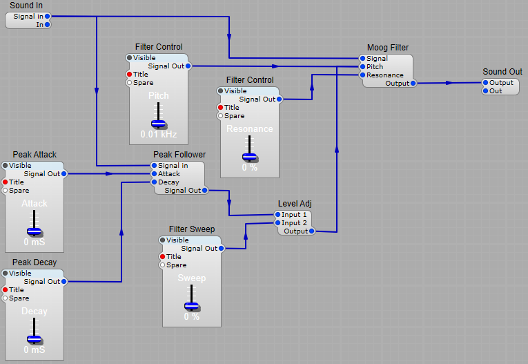
Adjusting the filter sweep.
This is quite simple, all we need to do is add a Level Adj module to the Signal Out plug of the Peak follower, with a slider control connected to input 2. There is no reason to stick to the Moog Filter for the audio filter, any type will do (as long as it’s a type that allows modulation of the pitch plug).
Set the controls…
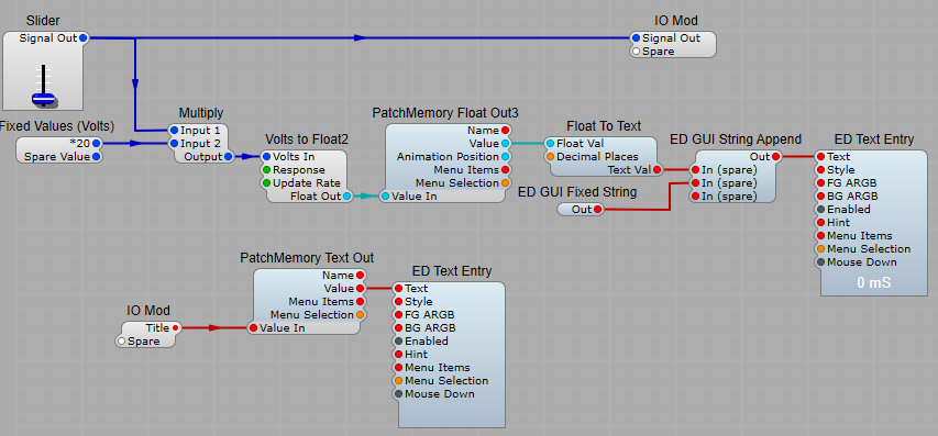
Peak Attack/Decay sliders.
You’ll see that these controls don’t look exactly like the standard SE sliders would.
Yes, I have modified them. The Peak attack and decay sliders have the following structure:
The only points of note are;
1) Multiply module is used to convert from Volts to mS, just set the value on the Input 2 plug to 20.
2) Volts to Float 2, Response should be Volts DC (fast), update rate 10 Hz.
3) Float to Text, set decimal places to 0 (none), we really don’t need to be that accurate!
4) ED GUI String Append, the second input plug needs to have a space before the mS text to read neatly. With this module the first plug will be the main value, and each spare plug will be appended text.
5) The two “floating” modules PatchMemory Text Entry, and ED Text entry are used to display the title of the control slider.
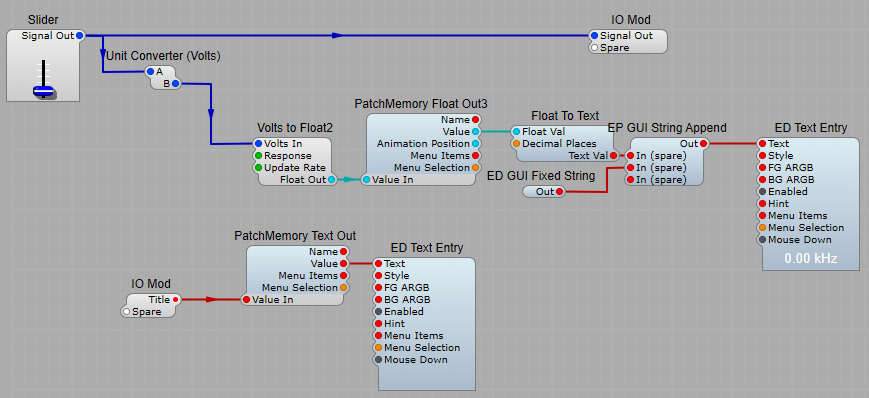
Filter control (Pitch).
There’s a conversion module used here, so we can display the filter frequency in kHz. Just use the Unit Converter (Volts) module, with its mode set to Volts to kHz, and change the text on the ED GUI Fixed String to read kHz (don’t forget the space at the start of the text!).
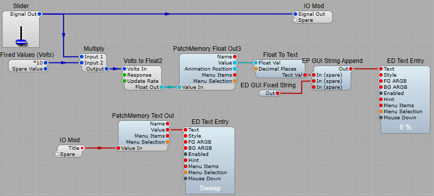
Sweep and Resonance sliders.
These are the same as the Attack/Decay sliders with two changes;
1) Multiply, the Input 2 is set to 10, so that we change the readout from 0 to 10 to 0 to 100.
2) Change the text on the ED GUI Fixed String to %.
This is quite a versatile module, it can be used (as I have shown) as a VST filter sweep effect, or you could modify it to include in a Synthesizer.
You could also modify the filter to make it into an “Auto-Wah” effect for use with a guitar or other instrument.
Leave a Reply