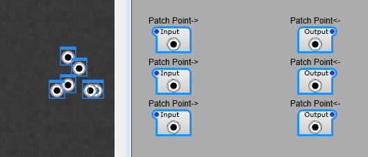
The existing Patch Point modules are fine, but a little basic. If you’re setting up a panel with a large number of patches you need to be very disciplined about labelling and arranging them. As I have found it’s too easy to get in a muddle. As you see below we can start with a nicely laid out pattern of patch points, switch to the panel view…and it’s chaos, and you have to select ech one, then switch to panel view and arrange everything. With some labelling the problem is solved, you can just arrange your panel view in one go.
Making life easier.
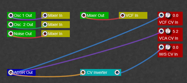
What would help is a text label and maybe some colour coding. We can do this fairly easily with a few sub controls. With a little planning we can produce a Patch Bay something like this… even having a few useful things like gain controls and inverters in the patch bay. Note: I’m sorry but the colours are limited to the patch points, there’s no way round this until Jeff introduces (please, please do this Jeff) colour customizable patch leads for the Patch Points. Also the transparency can’t be altered either. Patch cables are only fully visible when you hover the mouse over the patch point. Note: You can plug more than one cable into a Patch Point. Note: To disconnect a cable, right click on the Patch Point itself.
How the patch points are customized.
Not much to say about this really, this is just to point you in the direction of your own style of Patch Points and patch bay. Note: Do pay attention to the Z-order of the modules, otherwise you can end up with a hidden lable or Patch Point! From top layer down you want this order; 1) Patch Point 2) Text 3) The rectangle.
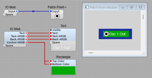
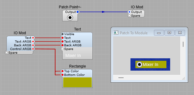
A Patch Point for connection to the Output of a module.
The plugs on the prefab are for controlling the appearance. (Apart from the input/output signals of course). Text: The is the lable next to the patch point Text ARGB: the ARGB colour settings for the label text Back ARGB: The ARGB Colour settings for the background of the text. You’ll most likely want to leave this as 00000000 (Transparent background) Control ARGB: The ARGB colour settings for the Rectangle used as the Patch Point background. Note: If you want rounded corners just go into the properties settings on the panel and adjust them.
Inside the Text container. This is containerized just to make the structure on this article a little easier to read
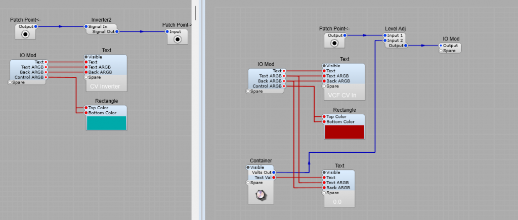
A Patch point for connection to the input of a module.
An Inverter patch point, and a gain control patch point. Just for ideas, really all sorts of patch points are possible from now on.
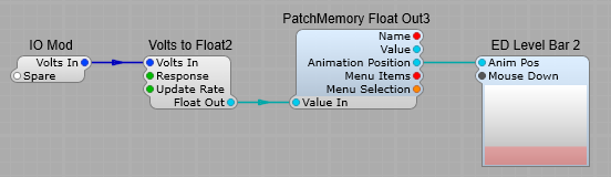
Using a drop down list to select between different control panels.
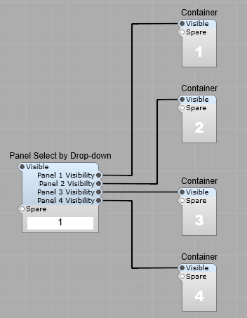
Using some simple logic , and SynthEdit’s ability to make the control panel of a container visible or hidden, we can easily switch between a variety of different control panels. Using this you could swap between say; 1) a standard oscillator, 2) A Supersaw oscillator, 3) A Casio CZ style phase distortion oscillator, 4) A Sample Oscillator.
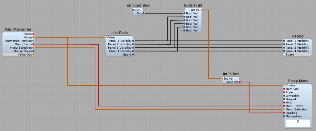
The Selector logic.
The Popup Menu module should have the following entered into it’s Item List box in the poperties panel 1,2,3,4 (No full stop or comma at the end of the list.) This value is selected from the popup menu, and sent via the PatchMemory Int module to the Int to Bools module. If 1 is selected the Int to Bools module then makes the output I have labelled as Panel 1 Visibility switch to “True”, and if 2 is selected the Int to Bools module then makes the output I have labelled as Panel 2 Visibility switch to “True” and so on. The Bools To Int is used to display the option you have selected in the Popup List. Note: You must have the First Bool Val connected and set to “False” with the ED Fixed_Bool module, otherwise the numbering will go out of sequence. The Int To Text is there to convert the numeric value back to a text string.
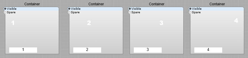
Inside the numbered containers I just put the following to test & demonstrate the sub control
As you select a number in the popup list on the panel, the number displayed will change to reflect your choice.
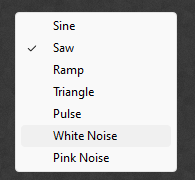
Yes you can, but only for for selecting options using the Many to 1 and 1 to Many flow switches. This is a useful but very poorly documented feature in SynthEdit. It only works when using the stock Popup Menu module, unfortunately the List Entry 4 module does not support this feature. Here is the popup menu we are all familiar with:
However with a little planning we can have a popup menu like this
The menu syntax
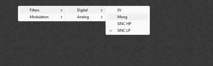
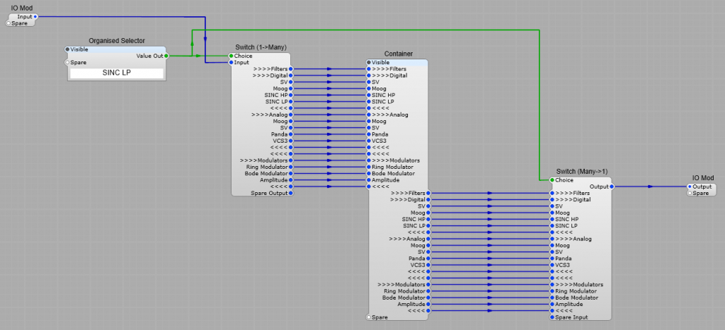
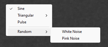
Using this structure below we can have our popup menu, organized into submenus. In this example we would have an arrangement where we switch between the selected modules , which would be kept in the container. As you can see some of the plugs on the switches have these groups of >>>> and <<<< symbols preceeding the text on them. This is the key to our sub menu system; >>>>Filters means “start a submenu called filters <<<< Means “end the submenu. You can add a submenu to a submenu like so; >>>>Filters >>>>Digital Filter 1 Filter 2 Filter 3 <<<< takes you back to the level Filters, to go back to the top menu level, add a second <<<< after the first. To add a spacer into the menu, just insert a —-.(four hyphens)
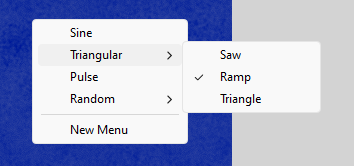
To create the menu below, you would use the following; Sine=0, >>>>Triangular, Saw=2, Ramp=3, Triangle=4, <<<<, Pulse=6, –, >>>>Random, White Noise=9, Pink Noise=10, <<<<, —-, New Menu,
Does the check mark for the selected item annoy or bother you? This can be removed by selecting a checkbox in the properties panel. If you check the “Momentary” option the check mark (tick) is no longer shown.
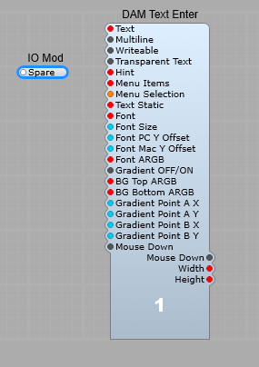
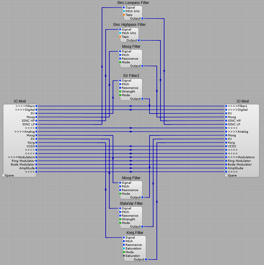
The structure inside the container is below, I have not shown too many modules, just enough to give you the idea. Important note. I have limited the modules shown below to keep things simple. When implementing this yourself please make sure there is a module that has no output such as a voltmeter connected to all the unused Inputs to avoid the “Hanging Modules” issue. Just put the module inside a container, and un-check the visible property so it remains hidden, it doesn’t have to be a Voltmeter, the volt meter module is special because it has no outputs and has a special flag set that tells SE’s “voice watcher” to ignore it. Other similiar modules should work too. . This is important as “dangling wires” can mess with polyphony sometimes.
Sub Menus for Modules with pre-defined Option Lists.
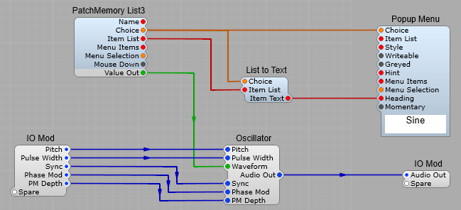
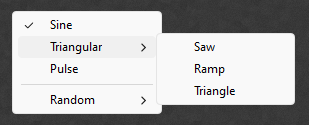
We can also use this with an Oscillator or Filter module. Do not connect the Patch Memory List’s Item List plug to the Popup menu, if you do you won’t get your Submenu system, just the default list of options. The menu system you want to use must be entered into the Popup Menu’s Item List in the properties panel.
Using the following item list will give you the menu shown underneath; Sine=0,>>>>Triangular, Saw=1,Ramp=2,Triangle=3,<<<<, Pulse=4, —- , >>>>Random, White Noise=5, Pink Noise=6, <<<<,
This project is an Attack-Decay envelope generator, with no “hold”, as soon as the envelope reaches it’s peak, it immediately begins to decay. There are three envelope curve options; Linear, Logarithmic and Exponential. The output level is controllable, inverted envelopes are specified by a negative gain voltage. All of the timings are in seconds per volt, there is no conversion needed between voltage and time.
This project relies on third party modules. These modules are available from Elena Novaretti’s website ED Glider 2, ED Log (Audio), ED Clip (Audio).
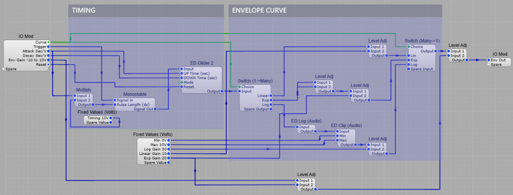
How the Timing section works.
A trigger pulse is received from the MIDI keyboard, or a suitable trigger source, this only needs to be a short pulse, no matter how long the trigger pulse is the envelope timing will not be affected. The attack control voltage is sent directly to the UP Time (sec) plug on the ED Glider 2 module, and to the Monostable Pulse Length via a Multiply module which has it’s Input 2 set to 10 (Attack V *10) as the timing voltage for the Monostable is in 1/10th Second per volt. This send a pulse with the same timing as the UP Time for the ED Glider 2 module (Without this the attack wouldn’t work for any timing except 0). The Decay control is sent directly to the Down Time (sec) plug.
Note: For the Envelope Generator to produce the correct results when used with a VCA module the VCA must have its response set to linear.
The Envelope Curve section.
Exponential: This uses a Level Adj module with Input 1 and Input 2 both connected to the output of the Glider module. This means that the output will be Input 1 * Input 2 converting a linear voltage envelope into an exponential curve. Linear: Is taken directly from the output of the Glider 2 module through a Level Adj module with its Input 2 set at 10. Logarithmic: The Glider 2 output is fed through the ED Log (Audio) module. There is a range Clipper on the output to ensure that the voltage cannot pass outside the normal 10V range (I found that sometimes negative voltages were being producedat the start/end of the envelope), and the Level Adj module to increase the positive output voltage to the normal level.
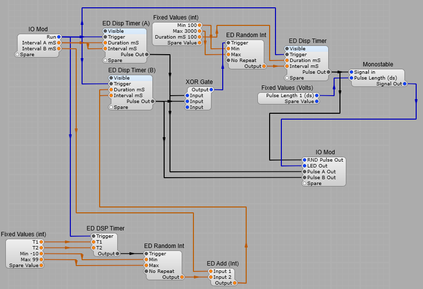
This module produces a random train of 100 mS long pulses, and a randomly varying control voltage, the minimum and maximum values of which van be varied.
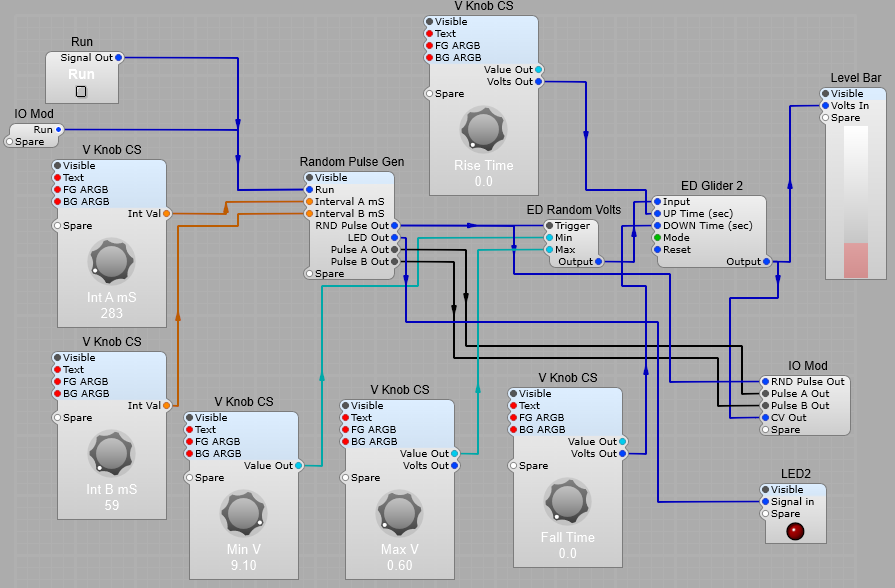
The Random Pulse Generator.
The principle of this module is that it produces two unsynchronized pulse trains running at different speeds. Pulse train B continually (1 second intervals) has a random value added to the Interval B mS setting by a an ED Random Int generator when the Module is triggered by a the ED DSP timer. Pulse train A and pulse train B are fed into an X-OR gate. This produces a pulse whenever A or B is high, but not when both are high. The result of this is a pseudo random chain of pulses sent to the ED Random Int generator which outputs a new integer between 100 and 1000 each time it receives a Trigger pulse. The random integer is then fed to the Final ED DSP timer which is set to produce 100mS pulses with an interval set by the Random Integer. This is fed to the RND Pulse out and a Monostable with the pulse Length set to 1 dS, this is used to flash an LED each time a pulse is output. The structure of the Random Pulse Generator is shown below.
Note: This project relies heavily on Elena Novaretti’s module pack. The modules used in the project are; ED Random Int, ED DSP Timer, ED Add Int, ED Level Bar 2, ED Random Volts, ED Glider 2.
The Level Indicator.
This is just used as a visual indicator of the CV level being generated.
The Complete CV and Timing Randomizer.
The RND Pulse out is fed into the ED Random Volts module. Each time this is triggered a new voltage is randomly generated. The Minimum and Maximum range of the output voltage is set bu the Min and Max knobs. The output voltage is fed to the ED Glider module. This module allows the rise and fall times to be set. The Glider mode should be set to constant time.
This design has a multiple VCO arrangement, this allows for morphing between Sine, Ramp, Triangle and pulse, as well as phase modulation. There is wavefolding on the Sine and Triangle oscillator outputs. The fifth oscillator has no audio output and is used purely to phase modulate the first four oscillators. The oscillator is fed to mutiple waveshapers which morphs bertween different waveshaping formulae. The waveshaping is based on the formula 5*sin(x/pi). The waveshaping is split into odd and even formulae with morphing between the two sections.
Five standard stock oscillators are used to allow morphing between the waveforms. Foldback is only used on sine and triangle wave shapes as the ramp and pulse shapes tend not to be worth wavefolding. The Sine 2 oscillator is used purely for Phase Modulation of the five audible oscillators.
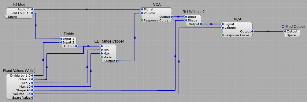
The wavefolder.
This relies on the RH-Wshape module fo gradually fold the waveform back on iteslf when it reaches a certain level. The amount of wave folding is controlled by the VCA on the input stage. Adjusting the CV range for better control. The ED Range clipper is used in combination with the multipler module so that the useful range of the Fold control voltage falls within the usual 1 to 10 Volts, otherwise the control was shomehat “cramped” as the useful voltage range without this conversion fall between 7 and 10 Volts. Input 2 of the divider is set to 1.5. The Range clipper is set to a Minimum of 7 volts and a Maximum of 10 Volts and the Mode is set to clip.
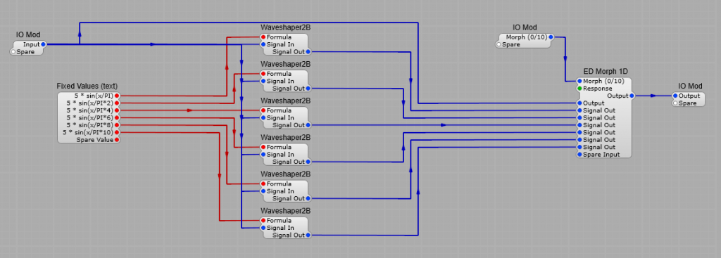
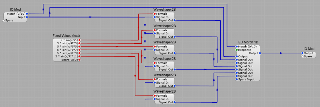
The Odd and Even wave-shapers.
I’ll describe both of these together. They are both made up of six Waveshaper2B modules using the formula 5*sin(x/pi) as a starting point. The formula changes slightly for each sucessive waveshaper. The ED Morph1D module at the output allows for a smooth morph between each formula. Each formula affects the harmonic content of the output in a different manner. The formulae are listed in the table below.
Even 5*sin(x/π) 5*sin(x/π*2) 5*sin(x/π*4) 5*sin(x/π*6) 5*sin(x/π*8) 5*sin(x/π*10)
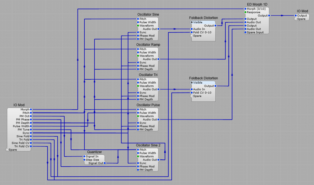
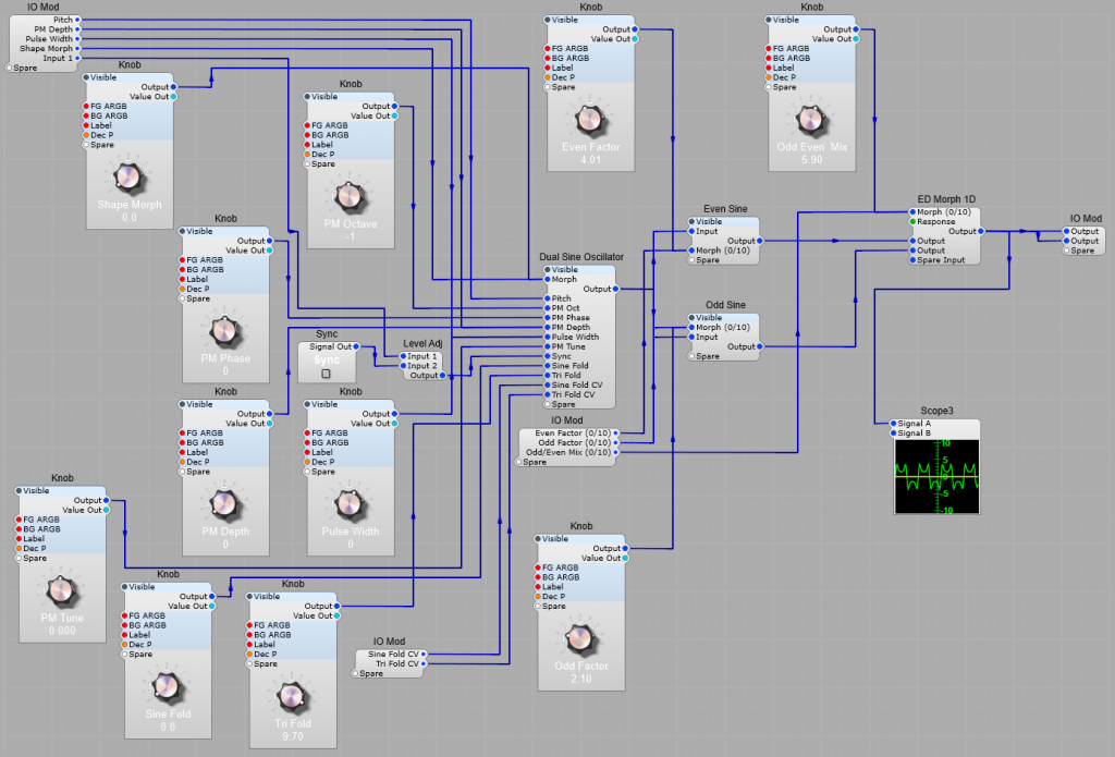
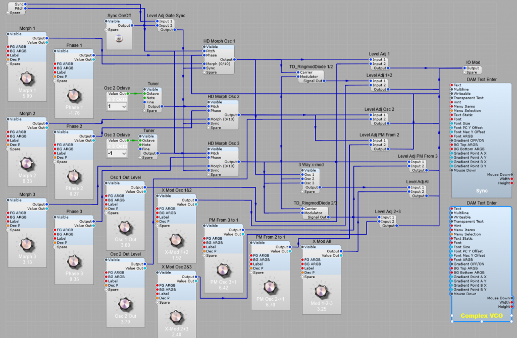
The complete Complex VCO structure.
All the main control settings on the Complex VCO can be modulated usin a CV within the range 0 to 10 V. The Scope3 module is optional, I just include it so the effects of changing control settings can be seen. There is a Sync connection so that the oscillators can be synchronized to a single source, this could be connected to the output of another oscillator, or to the keyboard trigger plug on MIDItoCV to ensure phasing between oscillators is always constant.
This is quite a complex project, so I will have uploaded a prefab to the files section of the groups.io website to study and experiment on. There are three Oscillators, all of which can morph between three wave-shapes; Sine, Triangle and Saw, the second Oscillator also has an audio output, but the third is purely for modulation of the other two oscillators.
The idea was to emulate (but not closely copy) the type of oscillators found in Buchla and some other types of (Eurorack?) modular synthesizers. It can produce a wide variety of output wave-shapes by using morphing between waveshapes, and using a mixture of AM and PM cross modulation. The sounds produced can vary between subtle harmonic changes, FM type sounds and some harsher, grating, metallic (less musical?) sounds.
Third party Modules.
There are a few third party modules in here: Elena Modules 1D Morph (No stock Equivalent) TD Modules RingMod Diode (This could be replaced with the stock Ring Modulator), but the sound is slightly different). The HD Oscillators are available from the community modules section on the SynthEdit website.
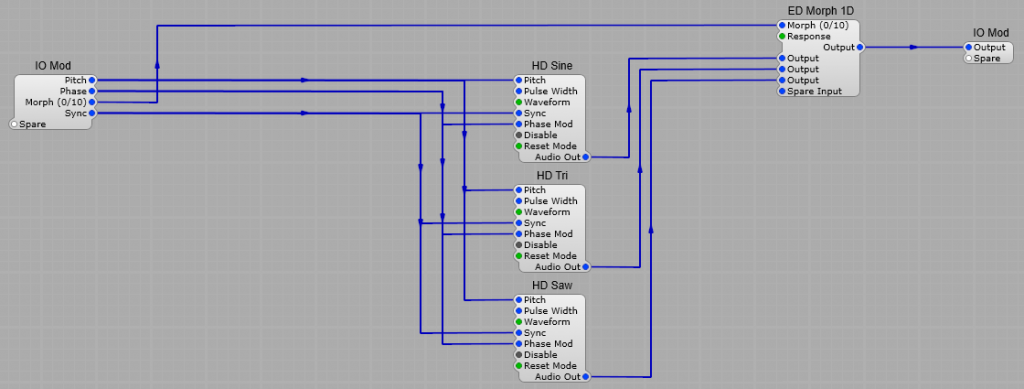
The morphing oscillators.
This is comprised of three HD Oscillators, all on the same pitch, which are left on pre-selected wave shapes; Sine, Triangle, and Sawtooth. The oscillator outputs are fed directly into an ED Morph 1D module which has the response setting Linear. This allows us to smoothly morph between the tree wave shapes. Leave the Oscillator reset mode on the DCO setting.
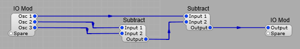
The 3 Way X-mod container.
This allows Oscillators 1, 2 and 3 to cross modulate their amplitudes by subtracting the output of oscillator 3 from the output of oscillator 2, then subtracting this signal from the output of Oscillator 1. Cross modulating the amplitudes of Oscillators 1 and 2, also Oscillators 2 and 3 is performed using TD RingmodDiode modules.
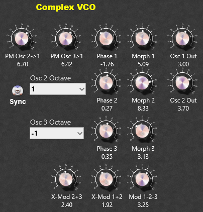
The complete Complex Oscillator.
Oscillator 1 is phase modulated by Oscillator 2 and 3, the PM amount is variable. Oscillator 1 is amplitude modulated by Oscillator 2, the AM amount is variable. Oscillator 2 is amplitude modulated by Oscillator 3, the AM amount is variable. Oscillators 2 and 3 can amplitude modulate Oscillator 1 together, the AM amount is variable. The start phase for all three morph oscillators can be set individually. All Oscillators can be Synchronized by a trigger pulse from the keyboard. This ensures that the output of the Complex Oscillator will be the same for each key-press on the keyboard. If you want variations is the sound for ech note played the Keyboard Sync can be turned off. The Octaves Of Oscillators 2 and 3 can be set above or below the pitch of Oscillator 1. Note about PM: Taking Phase Modulation to extreme levels and using wave-shapes with a sharp rise/fall time will cause a lot of high frequency harmonics, and quite possibly some aliasing by-products at the output.
Taking the Complex Oscillator further.
Of course being a VCO we will want to apply voltage control to some of these functions to allow further mangling of the wave-shapes, feel free to experiment, but I will be adding a new post on an updated Version 2 of this project in the near future.
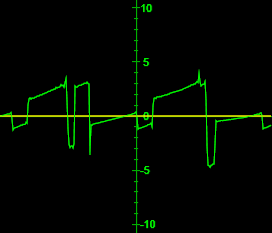
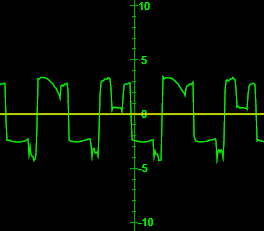
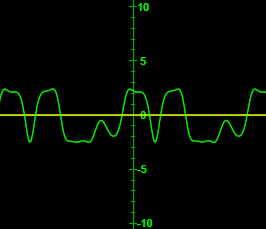
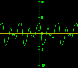
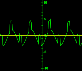
A few of the possible wave-shapes that can be obtained from the Complex Oscillator are shown below.
Post updated due to an error on my part when reading documents on the design of Buchla LPG module. 24/09/2025.
About Low Pass Gates (LPG).
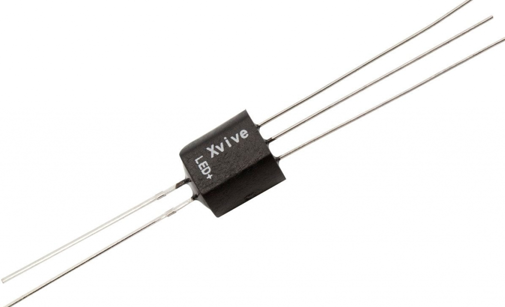
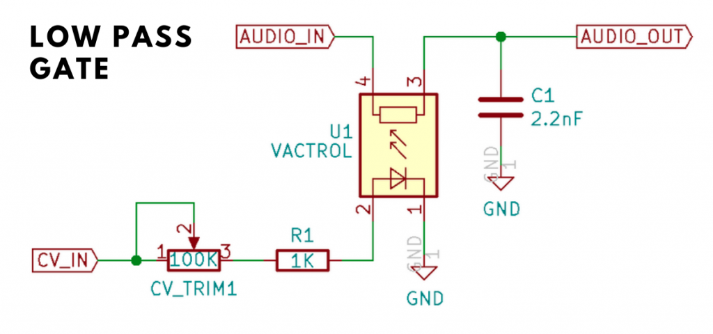
What is a low pass gate, and how does it differ from a normal low pass filter, isn’t it the same item with a different name? No It’s not. For a start the LPG doesn’t resonate in all modes. They were developed for the Buchla range of modular synthesizers, and have a more “acoustic” quality to them, think of the sound of a xylophone or bongos. Those instruments have a characteristic percussive and bright start to the sound, and the sound then quickly looses its brightness, and fades out slowly rather than dying away abruptly. This was a result of using a rather unique method of applying voltage control to frequency and amplitude, this was done with a device known as a “Vactrol”, which was a combination of a light source (early devices used a filament lamp, later ones used LED’s) and a light sensitive resistor (LDR). Below are shown a VACTROL device, and (for those interested a VCA circuit using a VACTROL.
As the voltage supplied to the light source got brighter the resistance decreased thus changing the volume or cut-off frequency. Due to the nature of both these components, there was a varying lag between light brightness and the resistance of the LDR Both these devices are non-linear in their characteristics, which vary between devices. This means it’s not something you can emulate precisely (it varied widely between modules-let alone synthesizers) , not that you need to as you’ll see later when we start putting our structure together. Although there is non-linearity, and a lag between voltage variations and the effect on audio there is no inherent distortion in the LPG to take into account (unless it’s overdriven of course).
Note: This project uses Two of Elena Novaretti’s third party modules: ED Exp, and ED Glider 2 (don’t use the Glider module, you can’t control the up/down times individually).
Generating the attack/decay envelope.
The Attack-Decal envelope for this project is different from the average ADSR envelope. We don’t need the Sustain and Decay portions of the envelope, just the attack and decay. You might think that having the the gate plug of the MIDI to CV2 module connected isn’t necessary, but I found that leaving the connection out caused some strange problems. For this reason I used a the Monostable to create a short pulse to trigger the ED Glider 2 module. One issue to take into account is that the ED Glider 2 module uses Volts per second for the Up and Down times, and the Monostable uses Volts per Deci-Second (10th’s of a second). For this reason I used a divider in the Rise time control line set to divide by 10 so that the Pulse out length from the monostable corresponds with the Up Time (Attack) of the Glide module. The pulse length needs to be the same as the Up Time for the Attack section of the envelope to work. The Down Time (Decay) portion of the envelope does not start until the input is at 0 volts. The Mode setting of the Glide 2 module should be left at the default Constant Time setting. The reset plug is not used.
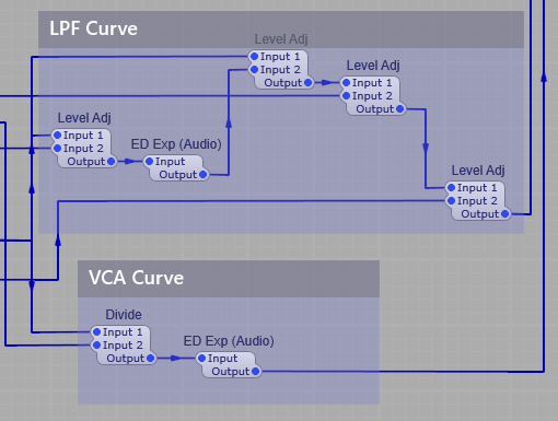
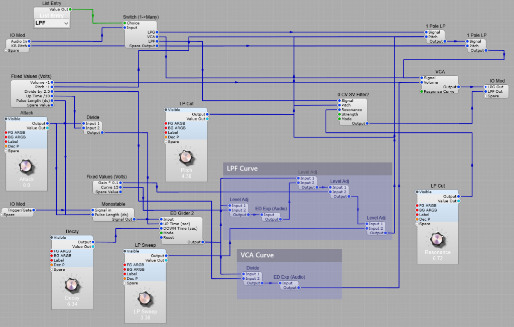
LPF Curve and VCA Curve.
You might think initially that having the two different methods of generating the curve for the envelope is a bit superflous, but I did this to imitate the effect that different Vactrol characteristics would have on the filter and VCA operation, so the envelope for the VCA is a straightforward exponential conversion, but the envelope for the Filter is quicker to decay meaning that when in the LPG option is selected the filtered sound will change in timbre more quickly than theloudness changes to give a more “percussive” sound to the output, where you get an initial bright start to the sound which then becomes naturally softer in timbre with the sound “ringing” on more than a conventional VCF/VCA combination.
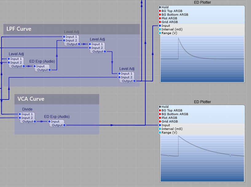
The screenshot below shows clearly how the CV curves for the LP Filter and the VCA differ in their curve, the LP Filter envelope decays quite quickly, whereas the VCA envelope has a far longer decay allowing the sound to “ring on” after the filter has reached it’s minum frequency (provided you leave the filter pitch at a point where the sound is still audible of course!)
Note: If the CV for the filter exceeds 10 Volts, most filters will internally “clip” this voltage to prevent the filter module from misbehaving, however the VCA module will oveload with CV exceeding 10V and produce some very harsh sounding (and very loud) clipping.
The filters
As the original LPG (Buchla) design had no resonance in it’s LPG mode I have just used two 1 Pole LP modules in series. There is no reason not to use an SVF or similar filter with resonance, but the aim here was to try and imitate the original design concept. If required you could use more filters to get a sharper Low Pass cut-off. Here comes the strange bit (well I think it is), when used just as an LPF the module did have resonance, so for this mode there is an additional SVF in two stage Low Pass mode, wired up as a seperate filter that only operates in this (LPF) mode.
The VCA
Although we are using an exponential CV envelope for the VCA, I found contrary to what I first expected the results sounded better if the Response Curve is left at the default exponential setting.
Voltage offsets.
The voltage offsets shown are to compensate for the effect of the exponential voltage conversion modules, to restore the correct 0 volts level for the “off” portion of the envelopes. Likewise we need the Level Adj modules to reduce the envelope voltages to their normal 10 V maximum. I used a fixed volts module to show the offset, gain and divisor values, and here’s a list of those values… List of offset voltage values; VCA Volume = -1V, (VCA Volume plug) Filter Pitch = -1V, (1 Pole LP Pitch plug) Divide by 2 = 2.5V (VCA Curve divider Input 2 plug) Up Time /10 = 10V (Divider for ED Glider module) Pulse Length dS = 0.1 (Monostable pulse length) Note: This offset is needed, if the Monostable Pulse Length is set to 0 it will not output any pulse at all. Gain *01 = 0.1V LPF (Curve Level Adj module Input 2) Curve 15 = 15 V (Divide Input 2 for VCA Curve) This affects how the initial decay curve of the exponential module feeding the VCA to imitate the differences in VACTROL characteristics. Note: Feel free to experiment with some of these values, but do be aware that we are dealing with exponentials and small changes can mean a large increse in output…make small changes incrementally. Be careful of your monitors/headphones and your hearing. Note: Changes in divide or gain module voltages will affect what voltage values you need on the LP Filter and VCA offsets.
Note: I have added a separate Output plug in this modification for the Low Pass Filter section, as this would need to be passed through a separate VCA anyway.
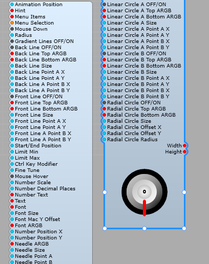
Hint: This is quite a complex module, so when I’m using it I tend to containerise it, then just connect up the plugs I know I want to use in my project so it’s a bit simpler to connect up and adjust the required settings.
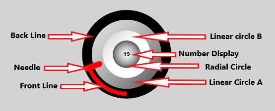
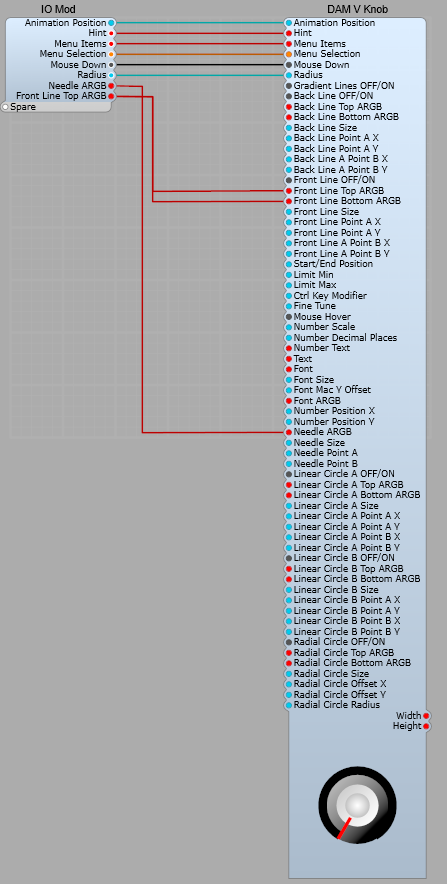
Animation Position: Bi-Directional plug both reports and controls the position of the control knob. Hint: Help text shown on mouse hover. Menu Items: Standard right click menu. Menu Selection: Standard right click menu. Mouse Down: Set the Bool Value when the mouse is clicked. Radius: Diameter of the entire control knob. Gradient Lines OFF/ON: Switches all the lines with gradient settings between single solid colour, and a gradient between two colours. This is a global setting for each control knob. Note: The lines cannot be switched between solid and gradient individually, the only way you could do this is to set all the lines as “Gradient” and then set the individual line(s) as required with the same Top and Bottom ARGB values.
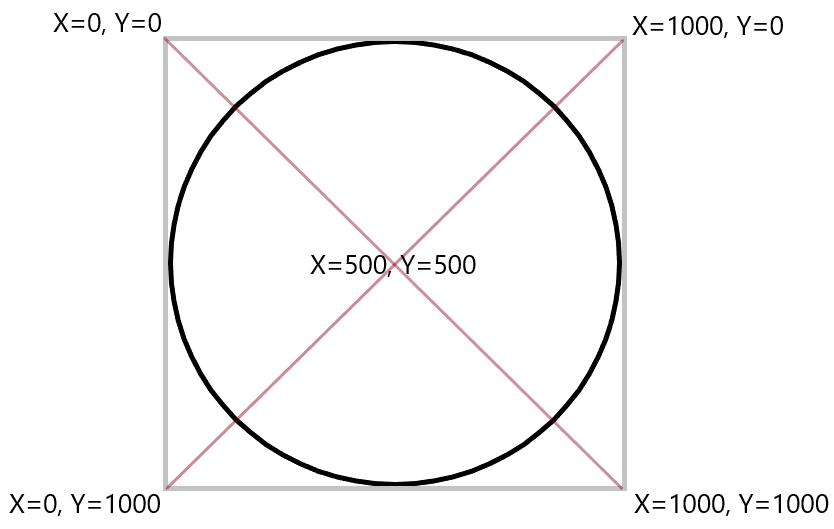
About the Back Line and Circle gradients.
The Back Line X and Y points for both line A and Line B are measured between the top left 0,0, and bottom right of the control 1000, 1000. These values are the same whatever the size of the control, so setting a line to 500, 0 will put A X halfway along the X axis, and the top of the Y axis. The diagram below shows the positions.
Back Line OFF/ON: Turns the Back Line off and on, this does not affect the Front Line settings. Back Line Top ARGB: Sets the Line A colour using ARGB. Back Line Bottom ARGB: Sets the Line B colour using ARGB. Back Line Size: Sets the width of the Back Line. Back Line Point A X:About Line and Circle gradients Back Line Point A Y:About Line and Circle gradients Back Line Point B X:About Line and Circle gradients Back Line Point B Y:About Line and Circle gradients Front Line OFF/ON: Turns the Front Line on and off. Front Line Top ARGB: Sets the Front Line A colour using ARGB. Front Line Bottom ARGB: Sets the Front Line B colour using ARGB. Front Line Size: Sets the size of the Front Line. Front Line Point A X:About Line and Circle gradients Front Line Point A Y:About Line and Circle gradients Front Line Point A Y:About Line and Circle gradients Front Line Point B Y:About Line and Circle gradients Start/End Position: Sets the Start and End points of the Front Line specified in degrees from the bottom of the knob, setting 90 will result in a 180 degree travel for the knob. The Start and End points are identical, they cannot be specified individually. Hint: setting Start/End Position to 30 will give you the same amount of rotation as a normal physical control knob. Limit Min: Sets the lower limit on the output value of the control knob. Limit Max: Sets the upper limit on the output value of the control knob. Note: Limit Min and Limit Max also effect the amount of rotation of the control knob. so if you have already restricted this using Start/End Position, these values will change the amount of rotation further. CTRL Key Modifier: Sets the control precision/rotation speed when the CTRL key is held down. Fine Tune: Sets the normal precision /speed of rotation. Mouse Response: Sets how the mouse interacts with the control. Mouse Hover: Number displayed: There are various options: None, no readout on the control at all. Animation Position, displays the animation position value only. Number Text, displays the text string sent to the Number Text plug. Text, displays the text string sent to the Text plug. This is the append/prepend text string so you can add text such as kHz, mS, dB etc. Animation Pos Append, displays the animation position followed by the string sent to the Text plug. Number Append, displays the string sent to the Number Text plug, followed by the Text plug string. Animation Pos Prepend, displays the string sent to the Text plug followed by the Animation position value. Number Pos Prepend, displays the string sent to the Text plug, followed by the string sent to the Number Text plug Number Scale: Sets the scale for the number displayed on the control when using Animation Position. This does not affect the output value. Number Decimal Places: Sets the number of decimal places used for the animation position value displayed. Font: Sets the font used for the value displayed. Font Size: Sets the font size for the value displayed. Font MAC Y Offset: Applies a Y position offset only on MAC computers. Windows PC’s are not affected by this value. This offset is used to compensate for the difference between Windows and MAC display graphics. Number Position X: Sets the horizontal position of the numeric display on the control knob. Number Position Y: Sets the vertical position of the numeric display on the control knob. Linear Circle A OFF/ON: Switches between a graduated and non-graduated fill. Linear A Circle fill: When set to a non-graduated fill the TOP ARGB is used. Linear Circle A Top ARGB: Sets the Top ARGB of the graduated circle Linear Circle A Bottom ARGB: Sets the Bottom ARGB of the graduated circle. Note: The Bottom ARGB is not used in a non-graduated fill. Linear Circle A Size: Sets the radius of the Linear A Circle. Linear Circle A Point A X:About Line and Circle gradients Linear Circle A Point A Y:About Line and Circle gradients Linear Circle A Point B X:About Line and Circle gradients Linear Circle A Point B Y:About Line and Circle gradients Linear Circle B OFF/ON: Switches between a graduated and non-graduated fill Note: The Bottom ARGB is not used in a non-graduated fill. Linear Circle B Top ARGB: Sets the Top ARGB of the Graduated Circle. Linear Circle B Bottom ARGB: Sets the Bottom ARGB of the Graduated Circle. Linear Circle B Size: Sets the radius of the Linear B Circle. Linear Circle B Point A X:About Line and Circle gradients Linear Circle B Point A Y:About Line and Circle gradients Linear Circle B Point B X:About Line and Circle gradients Linear Circle B Point B Y:About Line and Circle gradients Radial Circle OFF/ON: Turns the Radial circle off and on. Radial Circle Top ARGB: Sets the Top ARGB of the Radial Circle Radial Circle Bottom ARGB: Sets the Bottom ARGB of the Radial Circle. Radial Circle Size: Controls the size of the radial circle, as a proportion of the total size of the control knob. Radial Circle Offset X: Sets the horizontal offset. Radial Circle Offset Y: Sets the vertical offset. Radial Circle Radius: Sets the size of the radial circle.
Using the DAM V Knob.
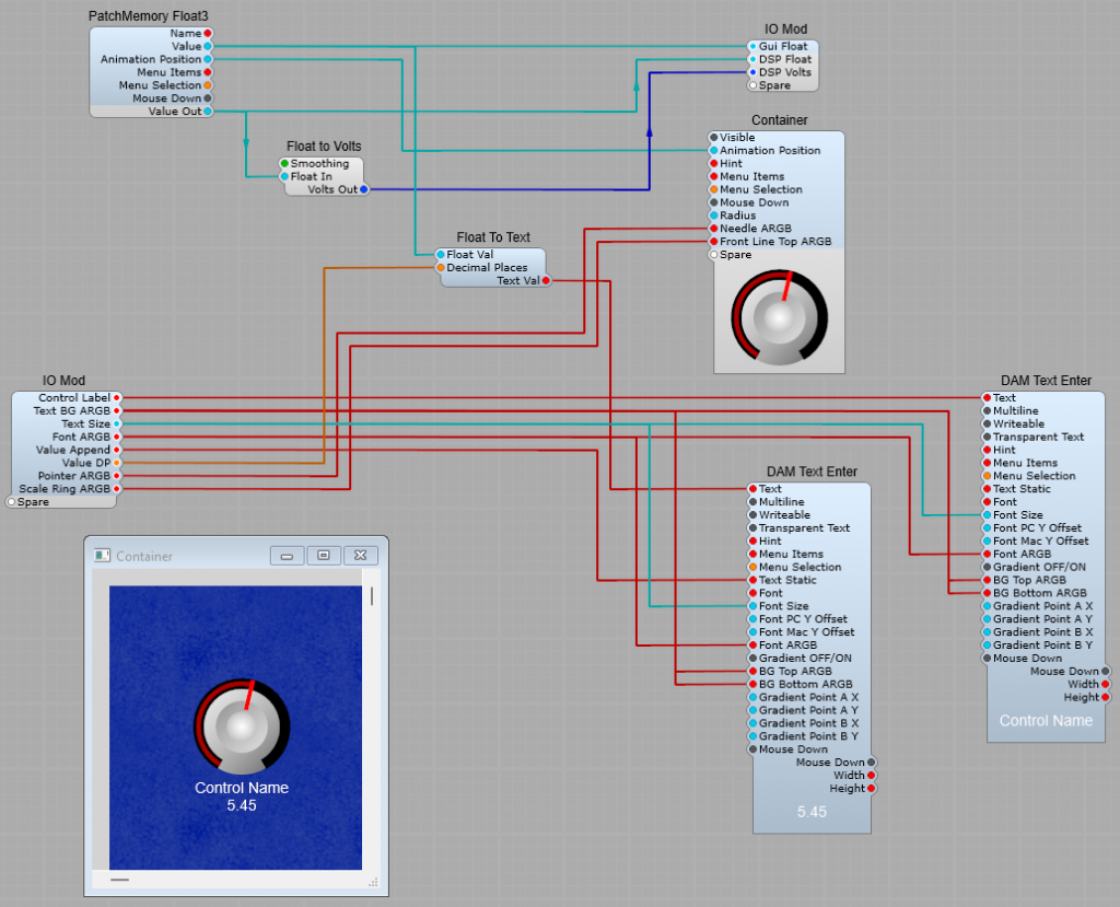
Here is a simple Sub-Control using the DAM V-Knob. You can see here I containerized the V Knob module itself to simplify things, so that we can just have the control plugs most likely to be used in plain view. Having the Control name and value readout below the knob is a personal choice (you can use the built in value display if you like). I have taken all three value outputs to an IO module to make the control more versatile. Hint: When making this sub control, start with the largest control knob size you’re going to use, its easier to scale it down than up. If you make a Sub Control, then increase the radius of the knob is will more than likely get cropped. Start with a large knob, then reduce the radius and you’ll have fewer problems.
The structure inside the container (Yes, Ok I forgot to rename it) is just the module, but I did this to make the Sub-Control easier to understand (and fit on my screen too!).