This is a handy little prefab, that’s easy to make. It’s useful if you have a slider with the range of -10 V to + 10 V, it can be fiddly finding the 0 V “null point” with the standard slider.
How the center return slider works.
The control works by having a button or other clickable item send a Mouse Down signal to a Spring module, which then sends a reset value of 0 volts to the Patch Memory, and the Image 2 slider control.
We need to make up the structure below inside a container. When we change the Image2 filename to “vslider_med.png” this will automatically load the instructions for how the control should behave, so leave this property setting as “Auto”. Likewise with the Image2 that has “button.bmp” loaded. By connecting the Mouse Down plug of Text Entry4 to the PatchMemory Float3 if we click on this text label it will also reset the control to 0 Volts. You should untick the Text Entry4’s writeable property so that it can’t be edited from the panel (it keeps it’s mouse down control output though). All we need to do is set the Reset Value for the Spring module to 0, the the prefab is completed ready to save and use The maximum and Minimum slider values can be set as normal in the Prefab properties panel when in use in SynthEdit. Note: Do not try and make the slider return to 0 V “on click” by connecting the Mouse Down plug for the slider control… it won’t work like that. As soon as you move the slider it will send a Mouse Down to the Spring, and as soon as you release the control it will snap back to 0 V.
This is another good module to gain an understanding of how sub controls work, and how the various modules interact.
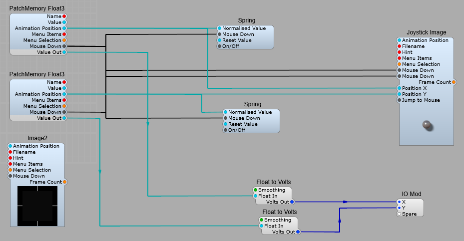
The Stock Joystick module
It’s all fairly standard stuff in this prefab, apart from introducing the Spring Module. The Joystick Image module reports both of the Joystick control image X and Y positions as floating point values in the normal default range of 0 to 1 (Position X and Position Y plugs). A static Bitmap Image provides the background for the joystick control. Scaled from 0 to 1, the X and Y Positions plugs are connected to the Animation Position input plugs of the respective PatchMemory Float 3 modules. The PatchMemory Float3 Low Value and High Value are set to −5 and +5, respectively, which are set in the Properties panel.
These modules scale the Animation Position to float values within this range, and the Floating Point values are then converted to Voltages by the Float to Volts modules, and the voltages are fed to the X and Y output plugs. When the user releases the left mouse button after clicking or dragging the joystick knob, the Mouse Down value changes from True to False, this value is then input to both of the Spring Modules which sets the Animation Positions to the default value of 0.5, thereby centering the joystick knob as soon as the left mouse button is released. The default return value is set in the Properties Panel (see below). For the X axis: 0 = Left, 0.5 = Centre, 1.0 = Right. For the X axis: 0 = Bottom, 0.5 = Centre, 1.0 = Top.
Creating a custom slider control from a joystick control.
Its suggested in the SE help file that using the stock Joystick Image GUI control is a good place to start creating your own slider control. You can, but I find a much better option is the third party ED Joystick Image control, as this allows you to “constrain” the movement of the control in the X or Y axis, whereas the native SE control doesn’t, meaning you can still move the control horizontally…not ideal. By constrain we mean that you can set limits on how far the joystick’s knob can be moved in the X or Y axis, so if we set a minimum of 0.5 and a maximum of 0.5 for the Constrain X Min, and Constrain X Max, and leave the Constrain Y values at their default of 0 for the Minimum, and 1.0 for the Maximum, then we will get a vertical slider control, with no possibility of horizontal movement.
The structure of our new slider control prefab. There’s nothing too unusual in here, just a few things need explaining. Module names: Slider = ED Joystick Image. Scale = Image2 (SE Sub-Controls) Title = Text Entry4 Value = Text Entry4 I have just renamed these to make it easier to see what’s going on. You won’t find the Slider knob image or the Scale image in SE, you would need to create these yourself. This can be done in Paintshop Pro, Photoshop or similar editing software by cropping the scale off the VSlider_Med.png image and saving the knob as Slider-Knob.png (for example) and copying and pasting the scale into a new image V-Slider-Scale.png (for example). Don’t use the existing file names as this will mess up the SE controls! Don’t forget to save them as .png to preserve the transparency. You can now modify the new slider scale to the length you can require, and stretch your new slider control to fit. Note: you cannot “stretch” or resize the images used by the SE Image2 Sub-control. The Patch Memory modules on the Title and Decimal point are to enable you to set your values for the control without opening it, and editing, however the values you set will no show until you run the audio engine. The CTRL Scaling Factor sets how finely you can control the slider when the CTRL key is held down. For most purposes the default of 0.1 is fine.
The finished prefab control. I have put in output plugs for GUI as well as DSP controls, including the animation position, whether you do so is entirely up to you. As the DSP Float output is taken from the Patch Memory Float3 it’s already normalized, and suitable for DSP usage.