Stuck with a SynthEdit project?

Tag: Control Knob

Sub Controls – Modifying the Knob

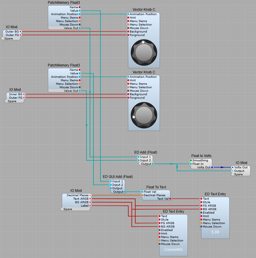
Have you Ever wished that the Moog style Knob control was just a little more versatile? Well it can be and it’s not “rocket science”. If we take the original Knob Sub-control prefab that comes with SynthEdit then its a matter of adding a few extra modules.

With some extra modules (as shown below) we can create a Knob which can be easily re-named, have a value readout, which has a suffix to indicate the type of value (Hz, Volts, dB etc.).
I have used the following ED modules:
GUI String Append, Fixed_string, and Text Entry (I like this module as it’s easy to control the appearance of the text, and set the background to transparent)
We also need to convert DSP Float values to GUI float values for the Hue switching so the QTN Float2GUIFloat is ideal here. The Bool to float modules are used so you can switch the Saturation from colour to mono, and the Brightness from light to dark using a simple tick/untick option.
With some basic maths we can re-scale the voltage to give us readouts such as; Volts->Hz, Volts->kHz, Volts->dB etc.
The switch with the fixed values allows us to easily select a text colour, or by unchecking the colour/mono option just to have black or white text.
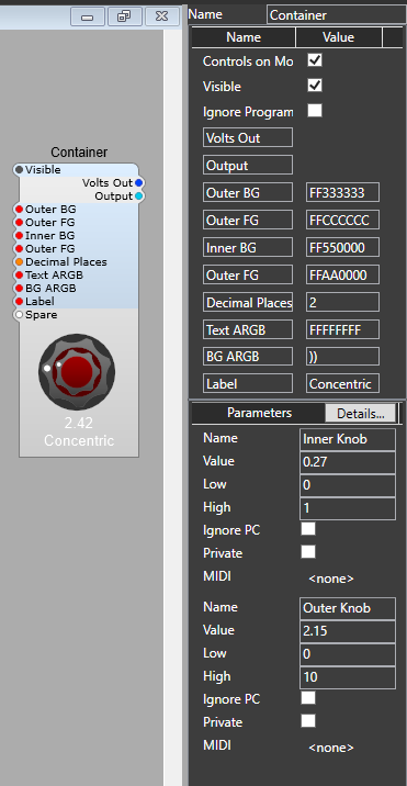
The Text and BG (Background) ARGB values are standard, and using 00 for the A value on the BG ARGB setting gives us a fully transparent background.
The string Append module allows us to add mode text after the Float To Text value, so there’s a single space in the Fixed String module, and then the third value is set by you for the appropriate Volts, Hz whatever for the control.
You can also change the number of decimal places that are used for the value readout using an integer value.

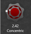
The finished control is shown below, and you can download the prefab (for V1.5) from here
Note: You must have the correct 3rd party modules installed!.

How the finished prefab looks

Concentric controls in Synthedit.

This is a method of creating a combined control for a coarse and fine voltage setting. It’s quite simple and uses the newer Vector controls. This is the finished control (Sorry that flashy looking knob in the centre is V1.5 only but the principle will work with the plain Vector Knob B in V1.4)

V 1.5 Vector Knob

How it looks using Vector Knob B in V1.4

V 1.4 control Knob

This is the structure below (Inside a container). We are just taking the Animation position of each vector control through a PatchMemory Float 3 to convert it to a DSP float value, this will later be converted to Voltage for DSP modules.
The PatchMem connected to the vector ring has its maximum value set to 1 so that we get a range of 0 to 1 for this control, and 0 to 10 for the Knob C. The two values are added together using an ED Add (Float) module, and converted to Volts for controlling DSP modules. This means we get a total range of 0 to 11 for the control (shades of Spinal Tap), so by setting the Knob C’s PatchMem to a maximum of 9, we go back to our usual default of 0 to 10 volts. All you need to do once its working is to create a panel view, size and line up the two controls then lock the container view and save as a prefab control.
This enables us to use the main inner knob as a coarse 0 to 10 control, and the outer ring as a fine 0 to 1 control (or any range you wish).

Changing the control ranges:

Changing the ranges for the inner and outer controls is as easy as setting the Max and Min values in the properties panel. This is set up for 0-to-1 for the outer ring, and 0-to-9 for the knob, giving an overall range of 0-to10 Volts out.

Two similar concentric knobs (V1.5 only)

The principle is similar, however I have added a text readout for the output value, and a text label for the control. Colours of the knobs and the text are editable too.

So this sort of control is possible.

And this is how it looks in panel view.