Post updated due to an error on my part when reading documents on the design of Buchla LPG module. 24/09/2025.
About Low Pass Gates (LPG).
What is a low pass gate, and how does it differ from a normal low pass filter, isn’t it the same item with a different name?
No It’s not. For a start the LPG doesn’t resonate in all modes. They were developed for the Buchla range of modular synthesizers, and have a more “acoustic” quality to them, think of the sound of a xylophone or bongos. Those instruments have a characteristic percussive and bright start to the sound, and the sound then quickly looses its brightness, and fades out slowly rather than dying away abruptly.
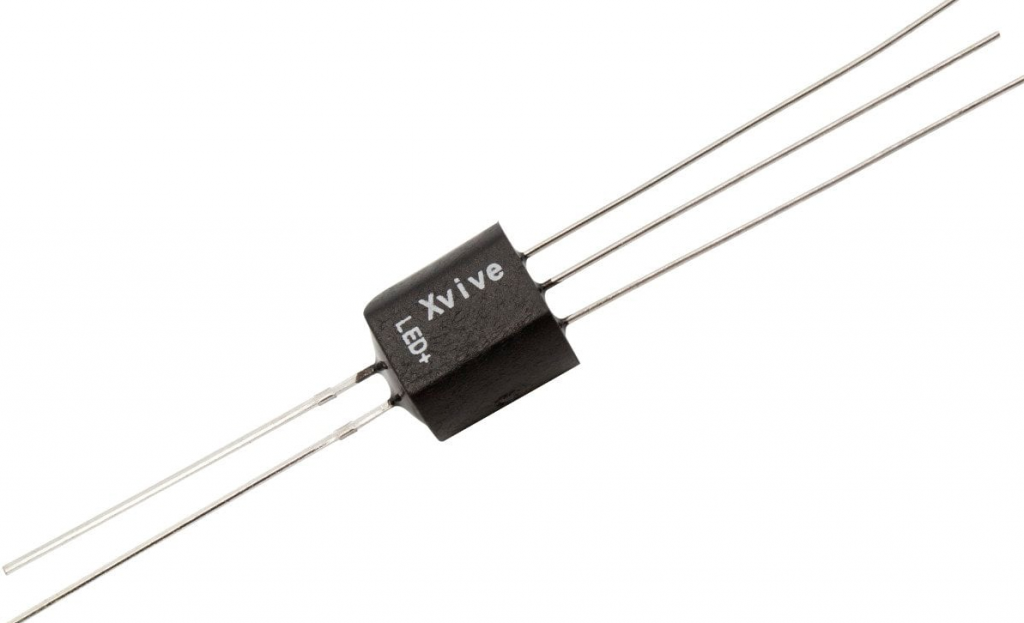
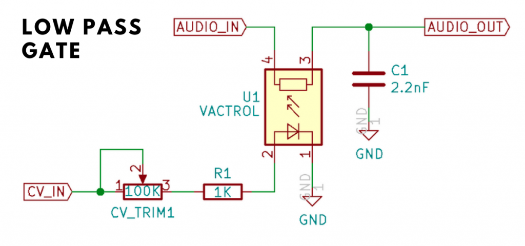
This was a result of using a rather unique method of applying voltage control to frequency and amplitude, this was done with a device known as a “Vactrol”, which was a combination of a light source (early devices used a filament lamp, later ones used LED’s) and a light sensitive resistor (LDR). Below are shown a VACTROL device, and (for those interested a VCA circuit using a VACTROL.


As the voltage supplied to the light source got brighter the resistance decreased thus changing the volume or cut-off frequency. Due to the nature of both these components, there was a varying lag between light brightness and the resistance of the LDR Both these devices are non-linear in their characteristics, which vary between devices. This means it’s not something you can emulate precisely
(it varied widely between modules-let alone synthesizers) , not that you need to as you’ll see later when we start putting our structure together.
Although there is non-linearity, and a lag between voltage variations and the effect on audio there is no inherent distortion in the LPG to take into account (unless it’s overdriven of course).
Note: This project uses Two of Elena Novaretti’s third party modules:
ED Exp, and ED Glider 2 (don’t use the Glider module, you can’t control the up/down times individually).
Generating the attack/decay envelope.
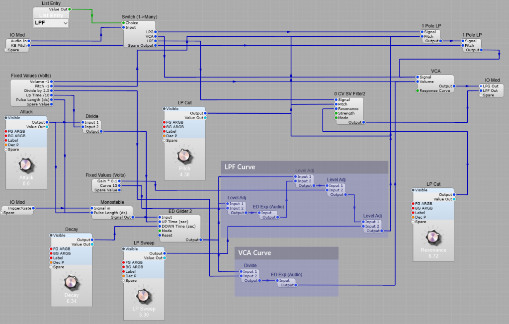
The Attack-Decal envelope for this project is different from the average ADSR envelope. We don’t need the Sustain and Decay portions of the envelope, just the attack and decay. You might think that having the the gate plug of the MIDI to CV2 module connected isn’t necessary, but I found that leaving the connection out caused some strange problems. For this reason I used a the Monostable to create a short pulse to trigger the ED Glider 2 module. One issue to take into account is that the ED Glider 2 module uses Volts per second for the Up and Down times, and the Monostable uses Volts per Deci-Second (10th’s of a second). For this reason I used a divider in the Rise time control line set to divide by 10 so that the Pulse out length from the monostable corresponds with the Up Time (Attack) of the Glide module. The pulse length needs to be the same as the Up Time for the Attack section of the envelope to work. The Down Time (Decay) portion of the envelope does not start until the input is at 0 volts. The Mode setting of the Glide 2 module should be left at the default Constant Time setting. The reset plug is not used.
LPF Curve and VCA Curve.
You might think initially that having the two different methods of generating the curve for the envelope is a bit superflous, but I did this to imitate the effect that different Vactrol characteristics would have on the filter and VCA operation, so the envelope for the VCA is a straightforward exponential conversion, but the envelope for the Filter is quicker to decay meaning that when in the LPG option is selected the filtered sound will change in timbre more quickly than theloudness changes to give a more “percussive” sound to the output, where you get an initial bright start to the sound which then becomes naturally softer in timbre with the sound “ringing” on more than a conventional VCF/VCA combination.

The screenshot below shows clearly how the CV curves for the LP Filter and the VCA differ in their curve, the LP Filter envelope decays quite quickly, whereas the VCA envelope has a far longer decay allowing the sound to “ring on” after the filter has reached it’s minum frequency (provided you leave the filter pitch at a point where the sound is still audible of course!)

Note: If the CV for the filter exceeds 10 Volts, most filters will internally “clip” this voltage to prevent the filter module from misbehaving, however the VCA module will oveload with CV exceeding 10V and produce some very harsh sounding (and very loud) clipping.
The filters
As the original LPG (Buchla) design had no resonance in it’s LPG mode I have just used two 1 Pole LP modules in series. There is no reason not to use an SVF or similar filter with resonance, but the aim here was to try and imitate the original design concept. If required you could use more filters to get a sharper Low Pass cut-off.
Here comes the strange bit (well I think it is), when used just as an LPF the module did have resonance, so for this mode there is an additional SVF in two stage Low Pass mode, wired up as a seperate filter that only operates in this (LPF) mode.
The VCA
Although we are using an exponential CV envelope for the VCA, I found contrary to what I first expected the results sounded better if the Response Curve is left at the default exponential setting.
Voltage offsets.
The voltage offsets shown are to compensate for the effect of the exponential voltage conversion modules, to restore the correct 0 volts level for the “off” portion of the envelopes. Likewise we need the Level Adj modules to reduce the envelope voltages to their normal 10 V maximum.
I used a fixed volts module to show the offset, gain and divisor values, and here’s a list of those values…
List of offset voltage values;
VCA Volume = -1V, (VCA Volume plug)
Filter Pitch = -1V, (1 Pole LP Pitch plug)
Divide by 2 = 2.5V (VCA Curve divider Input 2 plug)
Up Time /10 = 10V (Divider for ED Glider module)
Pulse Length dS = 0.1 (Monostable pulse length) Note: This offset is needed, if the Monostable Pulse Length is set to 0 it will not output any pulse at all.
Gain *01 = 0.1V LPF (Curve Level Adj module Input 2)
Curve 15 = 15 V (Divide Input 2 for VCA Curve) This affects how the initial decay curve of the exponential module feeding the VCA to imitate the differences in VACTROL characteristics.
Note: Feel free to experiment with some of these values, but do be aware that we are dealing with exponentials and small changes can mean a large increse in output…make small changes incrementally. Be careful of your monitors/headphones and your hearing.
Note: Changes in divide or gain module voltages will affect what voltage values you need on the LP Filter and VCA offsets.

Note: I have added a separate Output plug in this modification for the Low Pass Filter section, as this would need to be passed through a separate VCA anyway.
The LPG has resonance in lowpass mode, but no resonance in ‘both’ and ‘vca’ mode. It is a 2nd order filter in both and vca modes and a 3rd order filter in lowpass mode. Pretty weird. Check out the paper “A Digital Model of the Buchla Lowpass Gate” by Julian Parker.