What is the Harmonic Filter?
I can’t claim any orginal thinking on this idea. It was inspred by reading a PDF I found online.
Credit must go to:
Jae Hyun Ahn and Richard Dudas.
Center for Research in Electro-Acoustic Music and Audio (CREAMA).
Hanyang University School of Music.
The Idea is that you use either chained or nested comb filters to change the Harmonic spectrum of an audio signal.
Notes:
1) White and Pink noise just sounds like white noise put through a rather odd flanger.
2) The more harmonics the input waveform has, the more extreme the end result is. A sine wave will (apart from at resonance) still sound like a sine wave. As you increase the harmonic content things become more noticeable.
3) If you put the audio through a waveshaper and use extreme shaping levels the effect of this filter can become very strange.
4) Important. Beware of high feedback levels.
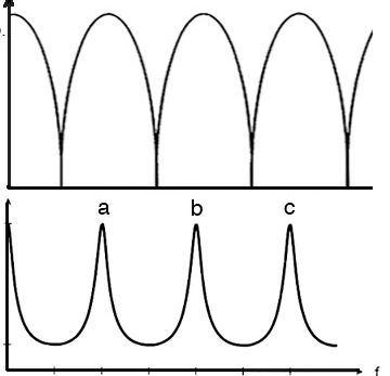
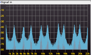
The concept is that with positive feedback in the delay line certain frequencies will be enhanced, and with negative feedback certain frequencies will be cancelled. By putting an offset on the frequency of either the posistive or negative feedback filters we can further change the harmonic structure. The diagram below shows the audio spectrum using negative feedback at the top, and positive feedback at the bottom. You can clearly see that one results in sharp notches removing frequencies (-ve), and the other results in sharp peaks (+ve) enhancing other frequencies.
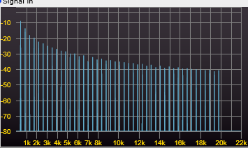
These screenshots will help to show some of the effects on a sawtooth signal:
First the unfiltered classic spectrum of a 440 Hz sawtooth
Then with 60% feedback, the filters set to 1kHz, and no offset.
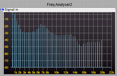
And with the same settings, but a +ve offset added to the +ve feedback comb filters.

You can see that by these changes to the comb filters the harmonic spectrum can be changed.
The sound the project produces (although I call it a filter) is quite unlike any other filter in the ususal synthedit modules. This is because we are boosting and cutting harmonics, rather than just cutting out frequencies, and also not always keeping these boosts and cuts harmonically related.
In the screenshots below using white noise as an audio source you can clearly see the peaks and troughs in the filter output, first with no comb filter offsets, then with a 200 Hz comb filter offset. The greater the feedback used in the comb filters, the more pronounced and narrower the peaks become.
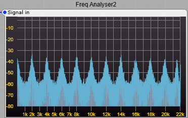
notice the new peaks appearing in the spectrum offset from the original peaks.
Note: For the curious amongst my readers, as an experiment I tried setting all comb filters with the same feedback polarity and testing. This does not produce the same results as having a 50/50 positive and negative feedback comb filter setup. It just produces a high level output with very wide single peaks and troughs. The 50/50 mix of positive and negative feedback are essential for this filter to work correctly. I found no benifit in changing this mixture of feedback, in fact the opposite was true.
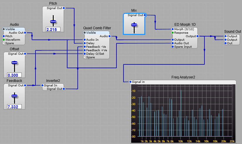
Constructing the Harmonic Filter.
This project uses a third party module.
The Filter wet/dry mixing uses the ED Morph 1D module. You could substitute the stock X-Mix module.
This is the basic structure, the Quad comb filter is a container, the structure of this is shown underneath the main structure.
Pitch control minimum and maximum values: Minimum = 0.5 Maximum = 5.
Offset values: Not critical, but +/- 0.3 is a good starting point, this corresponds to a shift of +/- 300Hz.
Feedback: A range of 0 to 7.5 is adequate, I would give 8 as the absolute maximum, don’t be tempted to go to 10, it will Oscillate very loudly.
Notes: The Freq Analyser2 module was for testing and showing the effect of the filter on the frequency spectrum, it can be removed if you want to. Likewise the Audio container is just for testing.
A prefab can be downloaded from Google Drive–Harmonic Filter for SE V1.5

All the Delay2 modules should have a Delay Time of 0.05 Seconds set in the propertioes panel (otherwise you get some very strange and unmusical things happening).
The two negative feedback filters have the same feedback level, as do the positive feedback filters. The Negative feedback filters get their feedback from the same control slider, they just have the value inverted so if the positive filters are set to +7, the negative filters are set to -7.
The Frequency (delay) offset is applied to both the positive feedback filters, but not the negative feedback filters.
Leave a Reply