Stuck with a SynthEdit project?

Category: VCA

Low Pass Gate Emulation.

Post updated due to an error on my part when reading documents on the design of Buchla LPG module. 24/09/2025.

About Low Pass Gates (LPG).

What is a low pass gate, and how does it differ from a normal low pass filter, isn’t it the same item with a different name?
No It’s not. For a start the LPG doesn’t resonate in all modes. They were developed for the Buchla range of modular synthesizers, and have a more “acoustic” quality to them, think of the sound of a xylophone or bongos. Those instruments have a characteristic percussive and bright start to the sound, and the sound then quickly looses its brightness, and fades out slowly rather than dying away abruptly.
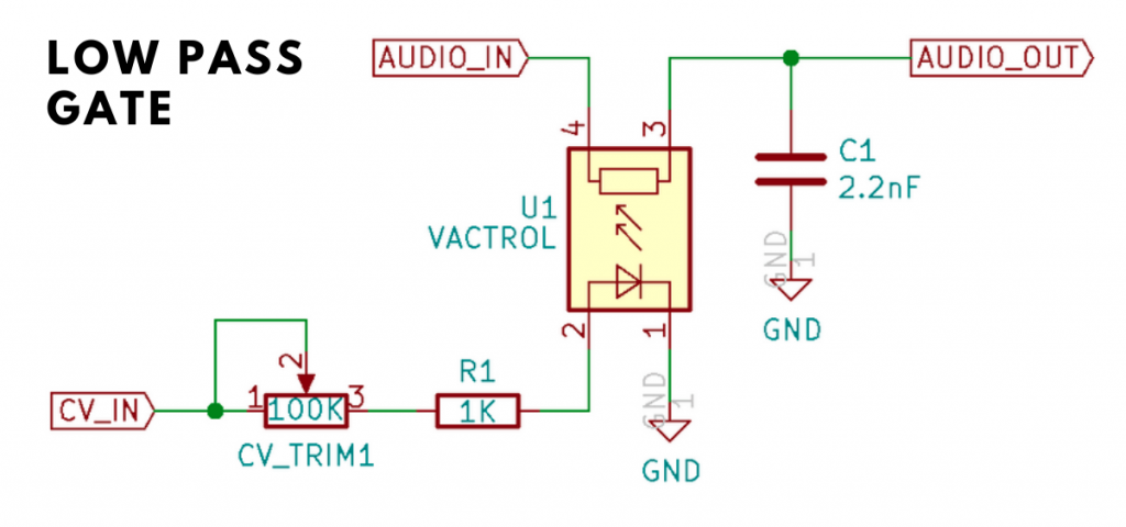
This was a result of using a rather unique method of applying voltage control to frequency and amplitude, this was done with a device known as a “Vactrol”, which was a combination of a light source (early devices used a filament lamp, later ones used LED’s) and a light sensitive resistor (LDR). Below are shown a VACTROL device, and (for those interested a VCA circuit using a VACTROL.
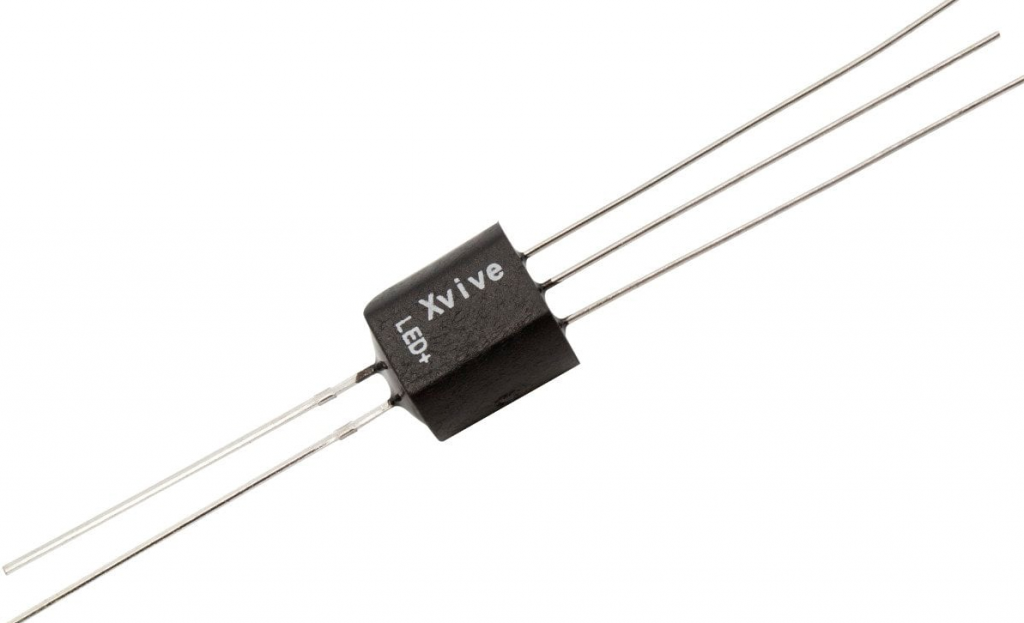
A VACTROL device
Using a VACTROL in a VCA

As the voltage supplied to the light source got brighter the resistance decreased thus changing the volume or cut-off frequency. Due to the nature of both these components, there was a varying lag between light brightness and the resistance of the LDR Both these devices are non-linear in their characteristics, which vary between devices. This means it’s not something you can emulate precisely
(it varied widely between modules-let alone synthesizers) , not that you need to as you’ll see later when we start putting our structure together.
Although there is non-linearity, and a lag between voltage variations and the effect on audio there is no inherent distortion in the LPG to take into account (unless it’s overdriven of course).

Note: This project uses Two of Elena Novaretti’s third party modules:
ED Exp, and ED Glider 2 (don’t use the Glider module, you can’t control the up/down times individually).

Generating the attack/decay envelope.

The Attack-Decal envelope for this project is different from the average ADSR envelope. We don’t need the Sustain and Decay portions of the envelope, just the attack and decay. You might think that having the the gate plug of the MIDI to CV2 module connected isn’t necessary, but I found that leaving the connection out caused some strange problems. For this reason I used a the Monostable to create a short pulse to trigger the ED Glider 2 module. One issue to take into account is that the ED Glider 2 module uses Volts per second for the Up and Down times, and the Monostable uses Volts per Deci-Second (10th’s of a second). For this reason I used a divider in the Rise time control line set to divide by 10 so that the Pulse out length from the monostable corresponds with the Up Time (Attack) of the Glide module. The pulse length needs to be the same as the Up Time for the Attack section of the envelope to work. The Down Time (Decay) portion of the envelope does not start until the input is at 0 volts. The Mode setting of the Glide 2 module should be left at the default Constant Time setting. The reset plug is not used.

LPF Curve and VCA Curve.

You might think initially that having the two different methods of generating the curve for the envelope is a bit superflous, but I did this to imitate the effect that different Vactrol characteristics would have on the filter and VCA operation, so the envelope for the VCA is a straightforward exponential conversion, but the envelope for the Filter is quicker to decay meaning that when in the LPG option is selected the filtered sound will change in timbre more quickly than theloudness changes to give a more “percussive” sound to the output, where you get an initial bright start to the sound which then becomes naturally softer in timbre with the sound “ringing” on more than a conventional VCF/VCA combination.

The screenshot below shows clearly how the CV curves for the LP Filter and the VCA differ in their curve, the LP Filter envelope decays quite quickly, whereas the VCA envelope has a far longer decay allowing the sound to “ring on” after the filter has reached it’s minum frequency (provided you leave the filter pitch at a point where the sound is still audible of course!)

Comparing the Filter and VCA envelopes

Note: If the CV for the filter exceeds 10 Volts, most filters will internally “clip” this voltage to prevent the filter module from misbehaving, however the VCA module will oveload with CV exceeding 10V and produce some very harsh sounding (and very loud) clipping.

The filters

As the original LPG (Buchla) design had no resonance in it’s LPG mode I have just used two 1 Pole LP modules in series. There is no reason not to use an SVF or similar filter with resonance, but the aim here was to try and imitate the original design concept. If required you could use more filters to get a sharper Low Pass cut-off.
Here comes the strange bit (well I think it is), when used just as an LPF the module did have resonance, so for this mode there is an additional SVF in two stage Low Pass mode, wired up as a seperate filter that only operates in this (LPF) mode.

The VCA

Although we are using an exponential CV envelope for the VCA, I found contrary to what I first expected the results sounded better if the Response Curve is left at the default exponential setting.

Voltage offsets.

The voltage offsets shown are to compensate for the effect of the exponential voltage conversion modules, to restore the correct 0 volts level for the “off” portion of the envelopes. Likewise we need the Level Adj modules to reduce the envelope voltages to their normal 10 V maximum.
I used a fixed volts module to show the offset, gain and divisor values, and here’s a list of those values…
List of offset voltage values;
VCA Volume = -1V, (VCA Volume plug)
Filter Pitch = -1V, (1 Pole LP Pitch plug)
Divide by 2 = 2.5V (VCA Curve divider Input 2 plug)
Up Time /10 = 10V (Divider for ED Glider module)
Pulse Length dS = 0.1 (Monostable pulse length) Note: This offset is needed, if the Monostable Pulse Length is set to 0 it will not output any pulse at all.
Gain *01 = 0.1V LPF (Curve Level Adj module Input 2)
Curve 15 = 15 V (Divide Input 2 for VCA Curve) This affects how the initial decay curve of the exponential module feeding the VCA to imitate the differences in VACTROL characteristics.
Note: Feel free to experiment with some of these values, but do be aware that we are dealing with exponentials and small changes can mean a large increse in output…make small changes incrementally. Be careful of your monitors/headphones and your hearing.
Note: Changes in divide or gain module voltages will affect what voltage values you need on the LP Filter and VCA offsets.
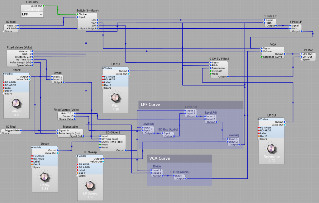
Note: I have added a separate Output plug in this modification for the Low Pass Filter section, as this would need to be passed through a separate VCA anyway.

The SynthEdit VCA Module

A VCA, or Voltage-Controlled Amplifier module, lets you use a voltage to control the amount of an audio signal that is allowed to pass through from the input to the output of the module.
The higher the control voltage, the more signal is passed.  In SynthEdit when the control voltage reaches 10V the entire signal is let through, and when the control voltage is 0V (or below), no signal is passed and the output is silent.

VCA or Level Adj. Which should I use?

While you could use the Level Adj module in place of the VCA, there are differences between the two modules. The VCA has a slightly faster response time to its Volume plug than Input2 on the Level Adj module. Also without conversion you’ll only get a linear response to the envelope, as opposed to the choice of curves for the VCA. Strictly speaking the Level Adj module is an audio voltage multiplier. When controlling audio volume or applying an audio envelope for best results the VCA should always be used.
The Level Adj module multiplies one input by the other. It can be used for ring modulation, or for amplitude modulation, or for scaling a signal/CV by a fixed amount. The two inputs are multiplied together, then normalised. (e.g. 5V multiplied by 2 V = 1V, (5 * 2 ) / 10).

Uses for a VCA module.

Volume Control
You can use your VCA to turn just about anything into a volume/level control. 
Run your audio signal through it, then connect the CV input to a mod wheel, or any voltage source you want.
Envelope Shaping
One of the most common uses of a VCA is envelope shaping. Think about when you hit a key on a piano; the amplitude starts out pretty loud, then over time it fades away.  If you let go of the key then the volume drops off pretty quickly. You can use a VCA in conjunction with an envelope generator to achieve the same effect with notes on your synthesizer.


An envelope generator (EG) is a module or circuit that generates a voltage that is triggered by something and changes over time.  If you’re trying to mimic a piano, you can configure the EG so that it is triggered by a key being pressed on your keyboard, it sends out a strong voltage at first, then it fades down to 0 over time.
The voltage sent out by the EG matches the way you want your amplitude to change over time.  Connect the output of the EG into the CV input of your VCA and it will cause the amplitude of your note to fade out like a piano note.
The structure shown below illustrates a typical ADSR/VCA combination to trigger an audio envelope from a MIDI input

The VCA response curve modes:

The VCA Module allows you to choose from 3 different response curves via a drop down list, or a selection in the VCA module properties:
1) Linear
2) Exponential
3) Decibel
4) Decibel (Old)
The following chart shows the relationship between input and output voltages

Comparing VCA response curves

A more useful graph is the output volume in decibels for a given input voltage. This shows more accurately how loud the signal sounds in relation to the control, voltage (below).

VCA loudness curves

This graph shows that volume plug input of 10 Volts produces full volume (or 0 Decibels), and an input of 0 volts effectively gives silence (-70 decibels, very quiet).
A full-scale audio input signal is -10 to +10 Volts.
The normal output range of SynthEdit’s Oscillators is -5 to +5 Volts (about -6dB).
Note: SynthEdit’s own VU Meter module displays an averaged signal. However you can switch it to peak mode.
What do the audio envelopes look like? All these sounds have the same ADSR envelope settings, but use different VCA modes.

1) Linear Mode.
This is useful for controlling the level of LFO’s or other modulation sources.
However for audio use such as a VCA this doesn’t sound like a natural audio decay to the human ear, as it seems to become faster as the level decreases.

Linear fade out

2) Exponential Mode:
This emulates the discharge rate of a capacitor (which is how an analogue ADSR works) and so is the closest reproduction of the audio envelope produced by an analogue synthesizer.
Given a volume from 0 – 10, this formula gives the output level in volts.
volts = 10 – c1 * (1 – e^( 3 * (volume / 10 – 1)))
Where ‘c1’ is a constant that determines the amount of curve:
c1 = 10 / ( 1 – e ^-3 )
c1 =10.524

Exponential fade out

3) Decibel (dB) Mode:
The human ear hears this as a constant, natural fade.
The Decibel curve drops by 35 dB between 10 – 1 Volt.
dB = (35/9) * ( volume – 1.f )
Volts = 10 * 10.f ^ ( dB * 0.5 )
Since a perfect dB curve can never reach zero volume in reality, the Synthedit VCA is designed so that below 1 Volt the VCA dB curve fades out to silence. This mode gives the most natural sounding VCA envelopes of all.

Decibel fade out

Converting Volts to dB

To convert a level in volts to dB, use the following formula:
dB = 20 × log10 (volts ÷ 10 )
To convert a level in dB to Volts, use the following formula:
volts = 10 × 10^ (dB ÷ 20)

Tremolo

Mix a slow sine wave with 8V DC from a Fixed Value(Volts) module (to make sure the whole sine wave stays above 0V), then feed this into the Volume Plug of your VCA.  The audio signal will mostly come through to the output because of the DC bias, but you will hear the amplitude get louder and quieter in time with the sine wave you are using to modulate it. 
This effect is called tremolo (Amplitude Modulation). In the screenshot below the Yellow waveform is the modulation sinewave and the green is our audio. You can see how the peaks and troughs in the audio level follow the modulating sinewave.
The slider control changes the level of the modulating sine wave, this works best with the maximum level set as 8V.
Note: For this effect to work correctly the response curve must be set as Linear.

Amplitude Modulation

Tremolo (shown above) uses a slow (say 3Hz for example) sinewave to modulate the amplitude of your audio signal, so you can actually hear the resulting loud/quiet cycles.  If you increase the modulating frequency so that it gets up into the audio range, however, things start to get interesting. 
The modulation has become so fast that you are now changing the shape of the original audio signal’s waveform, and new frequencies appear.
In the example below I have modulated a 7kHz sine wave with a 4kHz sine wave. As you can see in the Frequency analyser, not only do we have the 7kHz audio signal, but also two new frequencies have appeared at 3kHz and 11kHz. This is where the 4kHz signal has interacted with the 7kHz. Why 3 and 11 kHz? It’s because the frequencies are added and subtracted in the modulation process:
7kHz – 4kHz = 3kHz and 7kHz + 4kHz = 11kHz. This is similar to ring modulation, but there’s one key difference, with Amplitude Modulation the carrier frequency (the 7kHz signal) is still present at the output, whereas with a true balanced ring modulator only the new 3kHz and 11kHz frequencies would be present the 7kHz carrier having been suppressed.

Complex Amplitude modulation.

However it’s not always this simple to predict the results, if we modulate the 7kHz sine wave with a 4kHz sawtooth then the mathematics becomes more complex- we get many more frequencies added, (due to the more complex harmonic structure of the sawtooth)and would need to use Fourier analysis to predict the outcome.