Stuck with a SynthEdit project?

Month: January 2026

About sound: pitch, loudness, phase and harmonics.

This is a very basic overview, of some subjects that seem to cause misunderstandings and elements of confusion for some people.
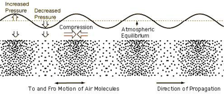
Sound is caused by an object vibrating and causing repeated compression and rarefaction of the air. These pressure waves impact on our eardrums and cause them to vibrate, sending small electrcal impulses to our brain. The same happens with a microphone, a small diaphragm vibrates with the pressure waves and converts the vibration into electrical signals.

Illustration of sound/pressure waves in air.

Volume, loudness or Amplitude:

The difference between the compression, and the rarefication of the air determines low loudly we percieve the sound. The greater the difference in pressure the louder the sound. Sound level is expressed as dB, the following list is a guide to loudness levels to give an idea of what this means to us;
0 dB – The softest sound a person can hear with normal hearing
10 dB – Normal breathing
20 dB – Leaves rustling, a ticking watch
30 dB – A whisper
40 dB – Refrigerator hum, a quiet office
50 dB – Moderate rainfall
60 dB – Normal conversation, dishwashers
70 dB – Vacuum cleaners, traffic
80 dB – Police car siren, a noisy restaurant- the level at which hearing damage can be caused by prolonged exposure.
90 dB – Hairdryers, blenders, power tools
100 dB – Motorcycles, hand dryers
110 dB – Nightclubs, sporting events
120 dB – Thunder, concerts, a jet plane taking off
130 dB – Jackhammers, ambulances
140 dB – Fireworks, gunshot.
Note: dB as a measurement does not relate in any real sense to voltage or wattage, it is really just a measurement of relative sound or signal levels, it’s really not as simple as saying for example that 100 watts of amplifier power output is equal to 80dB.

Frequency or pitch:

The spacing between the pressure changes determines the pitch, or frequency of the sound we hear. The closer together these pressure changes are the higher the pitch we hear. The human ear can detect these pressure changes when they fall between 20 times per second (20Hz), and 15 000 times per second (15kHz) and the upper limit of audibilty varies between each person. Pitch is the frequency translated into musical terms.

Harmonics:

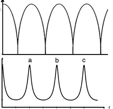
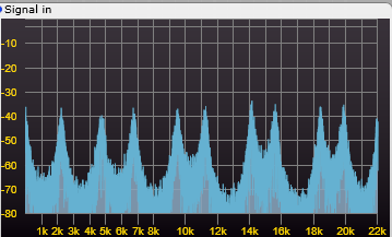
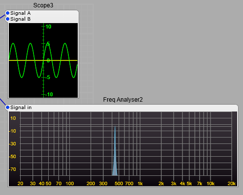
In the image showing pressure waves and how they relate to a sound, we saw a sine wave, this is a pure audio tone of one frequency. There are few (if any, excluding a synthesizer) musical instruments that produce a true sine wave. There will be a fundamental frequency. This is what we hear as the pitch of the instrument, as an example we will use standard A or 440 Hz. Below is our 440Hz sine wave and its frequency spectrum.

A pure 440 Hz sine wave, note how there is only the fundamental frequency, and no others.

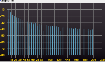
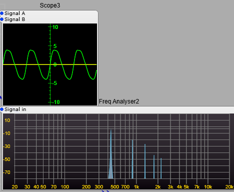
We may have an instrument that has a tone made up of the pitch we hear 440Hz, but it has other components. In most instruments such as a flute these will be directly related to our 440Hz pitch. They will be what are called Harmonics, and in most cases they will be at frequecies such as;
440 * 2 = 880 Hz which is the 2nd harmonic,
440 * 3 = 1320 Hz 3rd harmonic,
440 * 4 = 1750 Hz 4th harmonic,
440 * 5 = 2200 Hz 5th harmonic.
For each harmonic we multiply the fundamental frequency by the harmonic number, not the preceeding harmonic.
These harmonics will almost always be at a lower level than the fundamental.
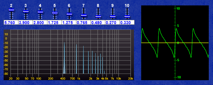
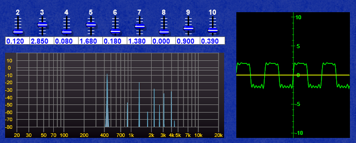
I have used these as an example below with decreasing levels, you can see the effect on the waveform.

The effect of adding harmonics to a sine wave.

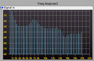
In the example below the 4th harmonic has been increased in level above the 3rd harmonic you can see how this has affected our waveform, this will have noticable changed the timbre of our sound but not the percieved pitch, as this is still the strongest of all the pitches.

The effect of incresing the strength of the 4th harmonic.

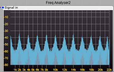
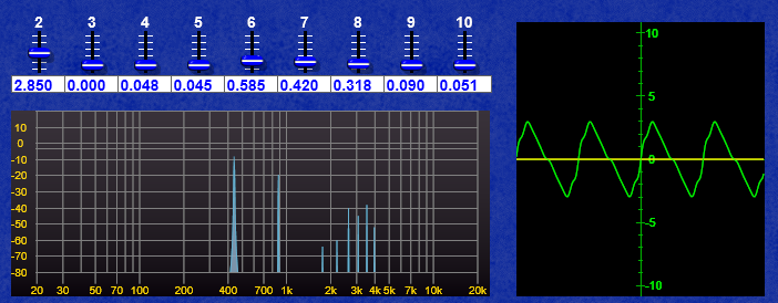
If we go as far as the 10th harmonic, then we can get a rough approximation of a sawtooth, with a bit of juggling with the levels.

Adding odd & even harmonics to produce a crude sawtooth

And by some juggling with the odd harmonics (3,5,7, & 9th) keeping the even harmonics low a crude approximation of a square wave.

Adding only odd harmonics produces a rough looking square wave.

Further juggling with even harmonics (2,4,6,8 & 10th) can get a wonky Triangle shaped wave.

Adding only even harmonics creates a wobbly looking Triangle wave.

Why are the harmonics so important? Where do they come from in physical instruments?

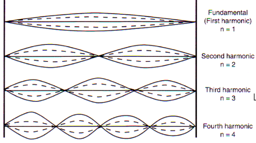
Why are these harmonics so important? Without getting too technical, and going deep into the theoretical side, musical instruments are usually a resonant string or tube (Very much over-simplified, but close enough). If we take a string and pluck it we will get a strong vibration the pitch of which is defined by the length of the string. However the string will also have other modes of vibration related to it’s length.

How harmonics relate to a string or pipe length.
How harmonics relate to the size of a string (or pipe)

Each of these is added to the fundamental, in decreasing amounts relating to a range of variables such as; string tension, string diameter, the materials in the string, how hard the string is plucked, and what the ends of the string are attached to (Not to mention the shape and size of the body of the instrument etc). The same principle applies to woodwind and brass instruments. The science of acoustic instruments and analysing or predicting the sound they produce needs some complex mathematics.
Where things get strangely different and eye wateringly complex is with percussion instruments…but that’s another very, very complex subject.

The complete science and analysis defining the sound produced by even a very simple physical musical instrument is very complex and requires a lot of complex maths.

What about Phase? What is it?

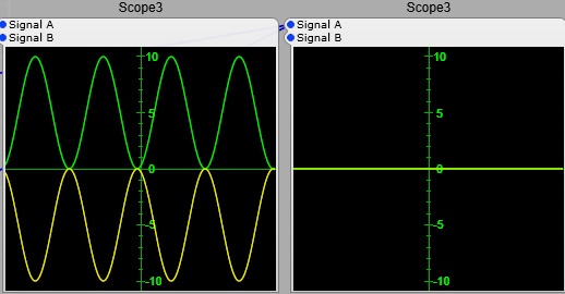
In the screenshot below we have two sine waves of the same frequency.

Two sine waves in phase
Two sine waves in phase (0 degrees phase difference).

See how they both start on the same part of the sine wave’s cycle. These are in phase, there is no time difference between them, and they have a phase difference of 0 degrees.. If you add the two waves together you’ll get another sine wave only twice the amplitude. 5+5 = 10, (-5) + (-5) = -10.
In the screenshot below the two sine waves are out of phase, and have a phase difference of 180 degrees. You can see that the two waves have cancelled each other. (+5) + (-5) =0.

Two sine waves out of phase.
Two sine waves out of phase, with 180 degrees phase difference.

When they are 90 degrees out of phase you get a partial addition of 5 + 2.5 = 7.5, and (-5) + (-2.5) = -7.5.

Two sine waves with 90 degrees phase difference.
Two sine waves out of phase by 90 degrees.

So if the phase between these two sine waves was to vary slightly over time you would get a “beating” effect as the two alternaltely fade between adding and cancelling. This is in effect what is happening when you have two sine waves of slightly different pitches, if the difference between the two sine waves is 0.5 Hz, then you would get a beating effect where the signals would fade between adding and cancelling every two seconds

"Beating" effect created by slight regular variations in phase, or a slight difference in frequency.
“Beating” effect created by slight regular variations in phase, or a slight difference in frequency.

The importance of phase and phase shift.

These effects caused by phase are very important to us in electronic music production, as phase differences can be used for positioning instruments in the stereo field and introducing changes to the harmonic structure (timbre) of the sounds. The effects apply equally to electronic audio signals and acoustic audio waves that you hear from a loudspeaker.
Note: Phase is not audible as such until we introduce a second audio signal into the mix where it will immediately change the timbre of the audio. If you have a single audio signal and vary its phase, you will not hear any difference, unless you were to take the original audio and mix it with the phase shifted audio, once you do this you’ll get a frequency notch where the two signals subtract from each other (the classic phasing effect). Small variations in frequency however are immediately obvious to most listeners without any second signal to refer to (unless you are totally tone-deaf).
An exception to the rule of phase changes being inaudible.
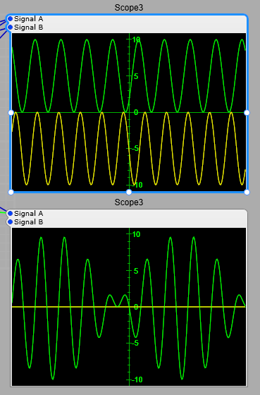
There is however an exception to phase changes not being audible: if a very deep and rapid change is made to the phase of an oscillator, you will get something called Phase Modulation or Phase Distortion, where this actually distorts the shape of a sine wave. This effect has been used to great effect notably in Casio CZ (Phase Distortion) and Yamaha DX FM synthesizers (strictly speaking this should be PM or Phase Modulation) synthesizers for example…but thats another complex subject. Just as an illustration in the image below the yellow trace is a 440 Hz sine wave with no phase changes, the green trace is a 440 Hz sine wave with a 10% shift in phase being applied by an 880 Hz sine wave.

The effect of Phase Modulation at audio rates. (440 Hz sine wave with 10 % phase modulation using an 880 Hz sine wave)

Phase and audio Mixing.

Phase is also important when it comes to converting a stereo signal to a mono signal. What sounds great in stereo may if there is a phase difference between left and right channels the mono audio will sound totally different, and may have a band of frequencies that are cancelling out boosting some frequencies and cutting others. It can also sound like a comb filter (flanger) being applied without any variation in the flanger delay time. All that careful mixing and equalization is quickly ruined. This could even be outside your control… music heard on a radio may not be heard in stereo for example.
This is where phase shift can become vital in tone control and equalizer plug-ins.

Harmonic Filter.

What is the Harmonic Filter?

I can’t claim any orginal thinking on this idea. It was inspred by reading a PDF I found online.
Credit must go to:
Jae Hyun Ahn and Richard Dudas.
Center for Research in Electro-Acoustic Music and Audio (CREAMA).
Hanyang University School of Music.

The Idea is that you use either chained or nested comb filters to change the Harmonic spectrum of an audio signal.
Notes:
1) White and Pink noise just sounds like white noise put through a rather odd flanger.
2) The more harmonics the input waveform has, the more extreme the end result is. A sine wave will (apart from at resonance) still sound like a sine wave. As you increase the harmonic content things become more noticeable.
3) If you put the audio through a waveshaper and use extreme shaping levels the effect of this filter can become very strange.
4) Important. Beware of high feedback levels.
The concept is that with positive feedback in the delay line certain frequencies will be enhanced, and with negative feedback certain frequencies will be cancelled. By putting an offset on the frequency of either the posistive or negative feedback filters we can further change the harmonic structure. The diagram below shows the audio spectrum using negative feedback at the top, and positive feedback at the bottom. You can clearly see that one results in sharp notches removing frequencies (-ve), and the other results in sharp peaks (+ve) enhancing other frequencies.

These screenshots will help to show some of the effects on a sawtooth signal:
First the unfiltered classic spectrum of a 440 Hz sawtooth

Unfiltered Sawtooth.

Then with 60% feedback, the filters set to 1kHz, and no offset.

And with the same settings, but a +ve offset added to the +ve feedback comb filters.

You can see that by these changes to the comb filters the harmonic spectrum can be changed.
The sound the project produces (although I call it a filter) is quite unlike any other filter in the ususal synthedit modules. This is because we are boosting and cutting harmonics, rather than just cutting out frequencies, and also not always keeping these boosts and cuts harmonically related.
In the screenshots below using white noise as an audio source you can clearly see the peaks and troughs in the filter output, first with no comb filter offsets, then with a 200 Hz comb filter offset. The greater the feedback used in the comb filters, the more pronounced and narrower the peaks become.

The harmonic filter output spectrum with no comb filter offsets.
The harmonic filter with a 200Hz offset on the second comb filter chain,
notice the new peaks appearing in the spectrum offset from the original peaks.

Note: For the curious amongst my readers, as an experiment I tried setting all comb filters with the same feedback polarity and testing. This does not produce the same results as having a 50/50 positive and negative feedback comb filter setup. It just produces a high level output with very wide single peaks and troughs. The 50/50 mix of positive and negative feedback are essential for this filter to work correctly. I found no benifit in changing this mixture of feedback, in fact the opposite was true.

Constructing the Harmonic Filter.

This project uses a third party module.
The Filter wet/dry mixing uses the ED Morph 1D module. You could substitute the stock X-Mix module.
This is the basic structure, the Quad comb filter is a container, the structure of this is shown underneath the main structure.
Pitch control minimum and maximum values: Minimum = 0.5 Maximum = 5.
Offset values: Not critical, but +/- 0.3 is a good starting point, this corresponds to a shift of +/- 300Hz.
Feedback: A range of 0 to 7.5 is adequate, I would give 8 as the absolute maximum, don’t be tempted to go to 10, it will Oscillate very loudly.
Notes:
The Freq Analyser2 module was for testing and showing the effect of the filter on the frequency spectrum, it can be removed if you want to. Likewise the Audio container is just for testing.

A prefab can be downloaded from Google Drive–Harmonic Filter for SE V1.5

Revised Quad Comb filter structure

All the Delay2 modules should have a Delay Time of 0.05 Seconds set in the propertioes panel (otherwise you get some very strange and unmusical things happening).
The two negative feedback filters have the same feedback level, as do the positive feedback filters. The Negative feedback filters get their feedback from the same control slider, they just have the value inverted so if the positive filters are set to +7, the negative filters are set to -7.
The Frequency (delay) offset is applied to both the positive feedback filters, but not the negative feedback filters.

1 Pole High Pass Filter.

This is aimed specifically at the stock 1 Pole High Pass Filter. What it is and what it’s useful for.

What is the 1 Pole HPF useful for?

Although it doesn’t have a steep cut off slope, and has no feedback/resonance control, this filter still has it’s uses. The idea of this filter is that all frequencies below the cutoff (pitch) frequency are attenuated by 6dB for every octave below the cutoff frequency. If for any reason you need a steeper cutoff slope just combine two or more in series. The only settings of note are;
Frequency Scale (Properties): Set to either 1 V/Octave or 1V/kHz.
Pitch: The cutoff frequency. Below this frequency the audio is attenuated with a slope of 6 dB/Octave.

1 DC Blocking.

Some structures may, due to the way they work may generate a DC component in their output audio. An example of this could be a waveshaper. This is undesirable as it can cause all sorts of issues such as assymetric clipping.
If you have an audio signal output at +/-5 volts peak to peak, and you have a +3 volts DC component, your +ve peal voltage is going to be 8 volts rather than 5, and if a sudden increase in audio occurs then you’ll quickly hit the +10 volts maximum for audio, and run into harsh, digital clipping. In the example below you can see where I have used (albeit a rather extreme wavshaping shape) a waveshaper and there is a noticeable peak showing at 10 Hz, which on it’s own could cause some audio issues, but also if you look at the voltmeter on the signal out plug of the wavehsaper we have 2.061 volts DC, which is exactly what we want to avoid. At the output of the 1 pole HPF (which I set to 100 Hz) however the 10 Hz peak in the spectrum is gone along with some others being much reduced, and we also lose that 2.061 V DC component.

Illustration of DC blocking with a high pass filter.

2 Effects such as Reverb.

Effects such as Reverb, Echo, Phasing and Chorus all sound much better if we apply a high pass filter to the audio input of the effect, it will sound much cleaner if a wide range of frequencies is being fed into the effect. Allowing lower bass (below 100- 200 Hz) frequencies into Reverb and Echo quickly makes the sound muddy, or even overpower the higher frequencies.

3 EQ and Mixing Plugins

There are several uses here, getting rid of low frequency rumbles, and hum which can quickly overwhelm a mix, or cause clipping. Use of High Pass filters on some instruments can also improve the clarity of a mix when used well.
Always include high pass filtering in any Mixer VST, Mixer Channel Strip VST etc.

DAM Chorus module.

The only third party module used in this project is the Chorus module itself.

The DAM Chorus Module plug layout.

Most of it is fairly self explanatory.
Mod depth: The maximum and minimum are 0 to 100, (that’s right 100 it’s not an error), this is the amount of modulation applied to the chorus delay time.
Mod Phase: Changes the phase of the modulation signals between Left and Right channels for stereo effects.
Width: Controls the Stereo Width.
Damp: Controls the amount of HF Damping. 10 = None, 0 = Maximum damping.
Feedback: Allows feedback in the signal path, this produces more of a Flanger type effect than Chorus at higher levels. Note: Some people seem to be confused by negative feedback, all this means is that the feedback is out of phase with the original signal, whereas the normal (positive) feedback we encounter is in phase. This changes the audio spectrum noticeably.
LFO Shape: Changes the waveshape of the modulation LFO. There is a choice of;
Sine, 3 Sines, Triangle, Parabola, and Random modulation.

The Chorus module in operation.

1 Pole HP filters are included (I Used 100Hz cutoff, but it’s down to your personal preferences) this stops the sound from getting too “muddy”. Bass in a chorus effect often doesn’t sound too good.
I have included the Voice Combiner modules in the structure because, if for any reason the module is in a Polyphonic signal chain you will get distortion, and it also wastes CPU.
Note: Don’t expect to hear too much of a stereo effect if your left and right channels are carrying identical audio, if everything is identical (phase, frequencies, volume) you’ll still essentially get a centred (mono) audio output.