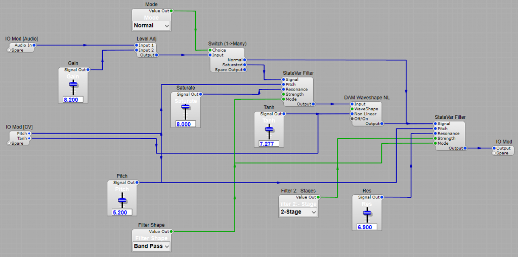
The stock Korg filters are fine, but suppose we wanted a more versatile filter such as an SV filter, but with that distinctive Korg MS20 style growl and scream? I can’t promise this is going to sound the same as the Korg, but it does have a wild overdriven sound to it. There’s only one 3rd party module used, the DAM Waveshaper NL (Thanks Davidson it’s a great addition to SE!)
The principle is fairly simple it’s a gain control on the input feeding the first SV filter which then feeds into the waveshaper. The first filter and the waveshaper can be switched out to give a clean SV filter sound. Normal/Saturated switching. On switching the extra filter and waveshaper in we can get the overdriven sound by adjusting the gain, the filter resonance (labelled Saturate) Note: You could leave it set as the default maximum of 10V but I found this tended to get a little too unpredictable. A maximum of 8 volts is plenty. Increasing the resonance will naturally increase the distortion from the waveshaper, but this is also controllable via the Tanh control. (I found the best waveshaper mode to be Tanh). Second filter. Nothing much to say here, it’s best however to keep the maximum resonance level to about 8 V to avoid self-oscillation. Modes. If like I have you want to make this a Low/High/Band/Notch filter then make sure both filters are connected to switch modes. 1/2 Stage switch. Best results for my ears came from just switching the output filter between 1 and 2 stage. I thought switching both made the filter to “thin” and shrill to be very musical. Control voltages. I kept the CV inputs down to controlling Pitch and Tanh, but feel free to experiment. Note: I tried adding an Pitch offset to the first SV filter in the chain, but I found the results were not too different.
Important note: When experimenting with this filter please, please, please keep the volume low until you are familiar with it. It will probably produce unexpectedly high volumes when resonant filter peaks start saturating. I would not like anyone to damage their hearing!
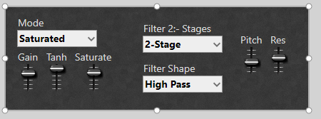
The Saturating SV Filter layout.The final panel layout
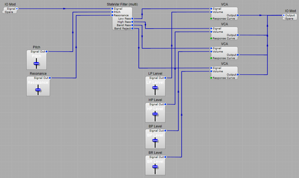
Using one of the StateVar Filter (Multi) can give us a very wide range of filtering options by mixing the outputs to combine their different characteristics in a number of ways.
Simple Low Pass filtering
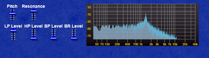
Combining Low pass and Band Reject filtering.
Note how in this example we get both a notch and a strong resonant peak.
Combining High Pass and Band Reject filtering.
Note in the HP/BR example the peak has now moved higher than the notch frequency.
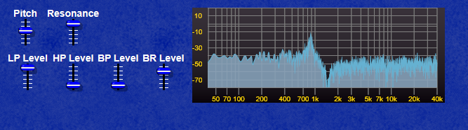
Combining Low, High and Band pass.
We now get a strong resonant peak giving a frequency boost, but not much in the way of any filtering out of frequencies.
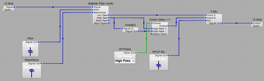
A two mode alternative to the four mode filter.
This model uses the same filter, but we only use the Low and High pass outputs. The Low pass is fed directly to one input of the X-Mix module, whilst the High pass has the option of being fed through an inverter. The inverter affects the output frequency spectrum. This is similar to those wonderful Oberheim Expander filters where you could cross mix the High and Low pass outputs. It won’t sound quite the same due to the chips that Oberheim filters used, but close to them.
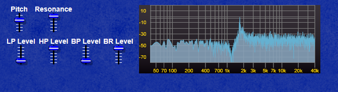
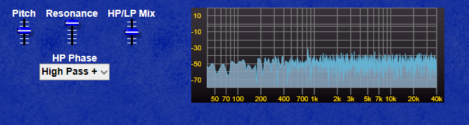
High Pass in phase.
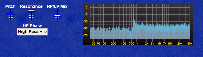
The frequency spectrum is fairly flat when HP and LP are in balance with no obvious resonant peak. Whereas below in the first example once the High Pass starts to predominate we get a notch with the resonant peak at a higher frequency.
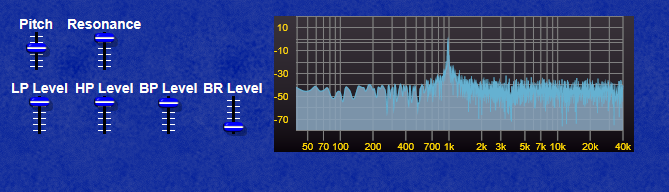
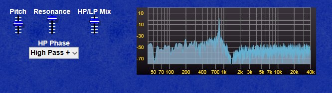
And in this example where the Low Pass is starting to predominate we get a notch with the resonant peak at a lower frequency.
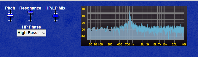
High pass out of phase.
By inverting the high pass output, we can create a strong resonant peak when both High and Low pass signals are in balance, whereas in the previous example where the High pass was not inverted the output is almost flat when the two signals are in balance.
A state variable filter is a type of active filter in electronic circuits. It consists of one or more integrators, connected in some feedback configuration (there are a few different methods of feedback). It is essentially used when a precise Q factor is required, as other multi-order filters are unable to provide. There are various design methods used in analogue circuits (which I won’t go into here), but they all give more or less the same results.
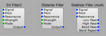
The choices of SV filter:
Note: State variable filters are all-pole filters, meaning they boost high frequencies even when the resonance value is low.
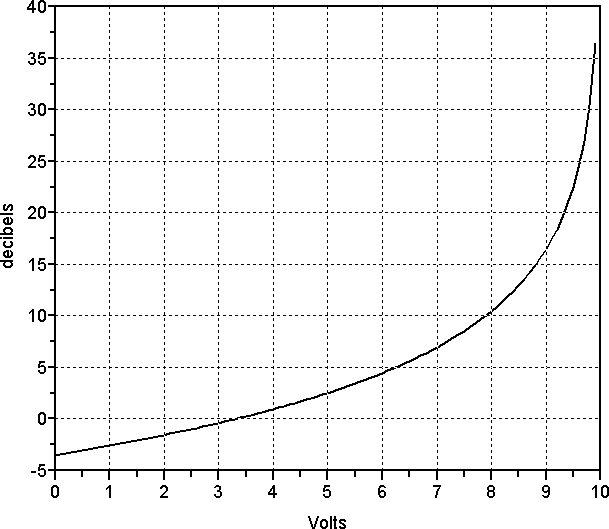
SV Filter2 – This one tends to be the one that has the most problems with overloading at high resonance levels. It has two “strengths” Single pole and Two Pole. In two pole mode the Low-pass and high-pass slopes are 12 dB per octave slopes, and band-pass or band stop (notch) modes’ slopes are 6 dB per octave. Also, the resonant response is nonlinear in the dB scale, as the graph below shows:
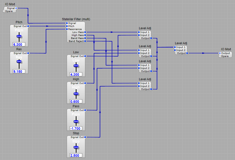
Around 10 volts, the resonance value skyrockets close to the point of self-oscillation. To prevent this, you may want to confine the resonance knob’s highest value to about 9 volts, or roughly 30 dB resonance. StateVar Filter – Much better behaved at higher resonance levels with the same switching between modes as the SV Filter2 StateVar Filter (Multi) – is essentially the same as the previous filter, but with separate outputs for Low, high, band pass and notch filter characteristics. This gives us all sorts of sonic possibilities by combining different filter outputs and mixing the levels. The four outputs will all change the signal’s phase in different ways, sometimes creating notches. Mixing Low Pass and High Pass outputs will create a band-reject filter. Negative voltages are perfectly acceptable on the Input2 plug of the Level Adj, so entering something like 10 for low pass and −10 volts for high pass means that the High pass level adj will invert the signal and subtract the high-pass from the low-pass output. This produces a flat response with a resonant peak at the cutoff frequency, which is great for adding resonant peaks to a signal. Note: State variable filters are all-pole filters, meaning they boost high frequencies even when the resonance value is low. This affects band-pass and high-pass outputs more than the low-pass output. And mixing these outputs adds a touch more gain. See the structure below for setting up a mixable SV Filter:
VA State Variable filters. These are the updated versions of the older filters listed above, and they do have an improved high frequency range, and better stability, but still need normalizing, and the Resonance limiting To 9V VA State Var VA State Var (Multi)
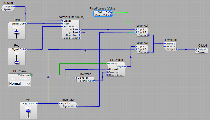
“Oberheim” style SV Filter
This filter takes the High and Low pass filter outputs and mixes them in variable amounts with the option to invert the phase at the output of the HP filter. This structure provides a wide range of sonic possibilities ranging through High pass, Low Pass, Bandpass, Notch, and resonance effects. The best way to find out what it’s capable of is to connect up a white noise source at the input, and have a listen (it’s also interesting to connect up the Frequency Analyser too) I found the best results were with the mix slider set with a range of 0 to 15V and a fixed value of 15V on the Level Adj in the Low Pass signal line.
Taming the SV filter.
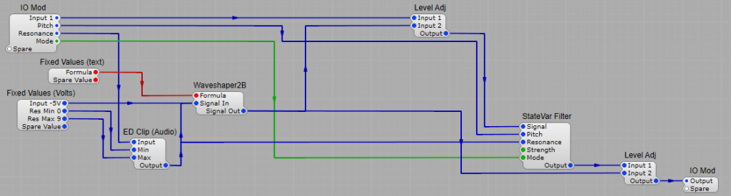
The SV filter is versatile, but at higher resonance levels, the gain can increase to the point of clipping, this is not good, because whilst it may sound fairly good when an analogue SV filter overloads, the Synthedit module will produce some really harsh distortion. Fortunately there is a way to tame this versatile filter, with Level Adj modules, and the Waveshaper. By taking the Resonance control voltage, by the way it’s always good to limit the rage of the resonance- I have done it here using an ED Clip (Audio) module to limit the resonance to 9V, rather than the maximum allowed of 10V. Too much resonance and the filter will self-oscillate and overload. By taking our resonance control voltage and feeding it through a waveshaper using a formula of 10-(x+5)x0.55 we can control the input and output gain in the Level Adj modules to get a fair approximation of constant signal levels at resonance settings between 0 and 9. This can be applied to all versions of the SV filter.
Note: Although the StateVar filters are better ‘behaved’ than the SV filter at higher resonance levels, adding this normalization to the filters is still worthwhile.
Credit: The Normalization structure is an adapted & updated version of the original from the book: Visual VST/i-Programming by H. G. Fortune (Editor), Peter Schoffhauzer, and David Haupt.