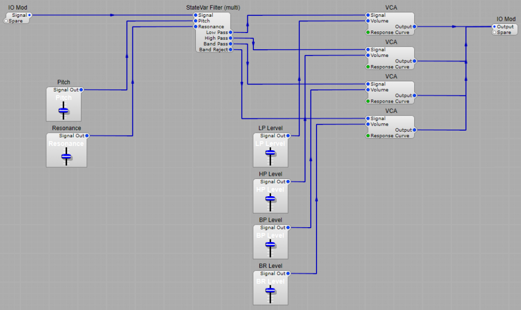
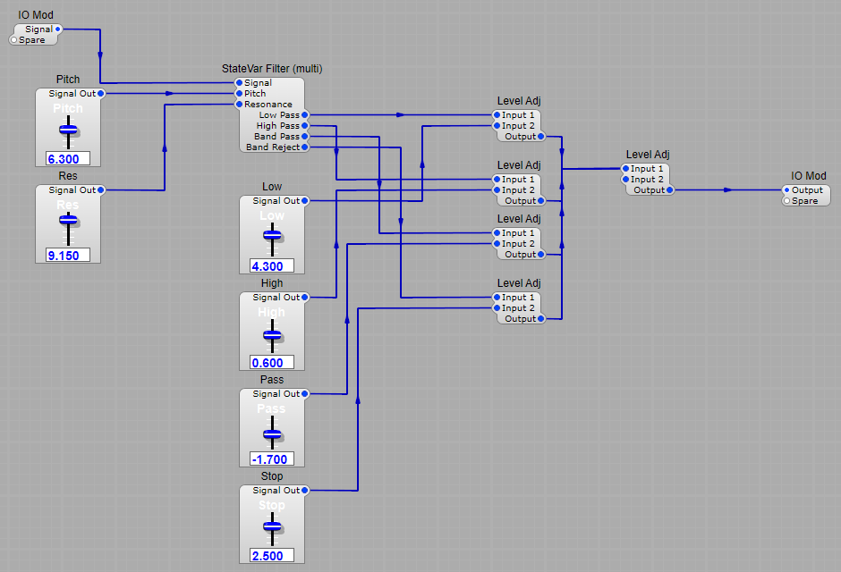
Using one of the StateVar Filter (Multi) can give us a very wide range of filtering options by mixing the outputs to combine their different characteristics in a number of ways.
Simple Low Pass filtering
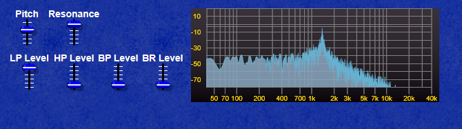
Combining Low pass and Band Reject filtering.
Note how in this example we get both a notch and a strong resonant peak.
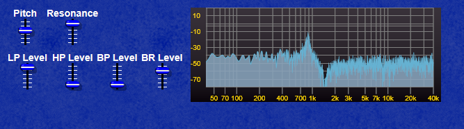
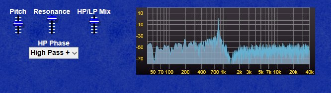
Combining High Pass and Band Reject filtering.
Note in the HP/BR example the peak has now moved higher than the notch frequency.
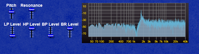
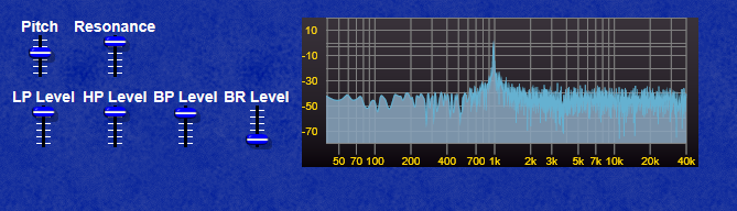
Combining Low, High and Band pass.
We now get a strong resonant peak giving a frequency boost, but not much in the way of any filtering out of frequencies.
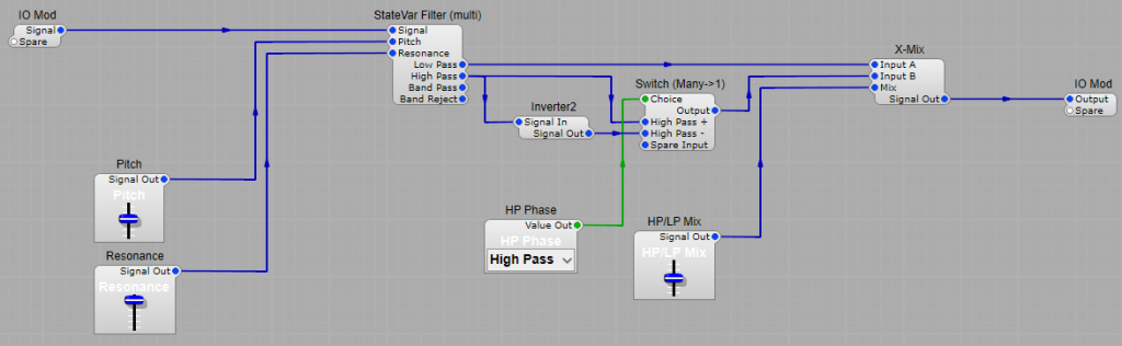
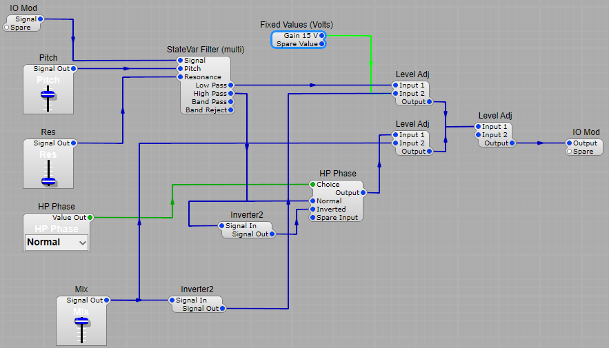
A two mode alternative to the four mode filter.
This model uses the same filter, but we only use the Low and High pass outputs. The Low pass is fed directly to one input of the X-Mix module, whilst the High pass has the option of being fed through an inverter. The inverter affects the output frequency spectrum. This is similar to those wonderful Oberheim Expander filters where you could cross mix the High and Low pass outputs. It won’t sound quite the same due to the chips that Oberheim filters used, but close to them.
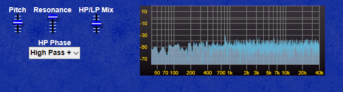
High Pass in phase.
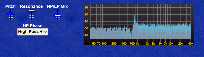
The frequency spectrum is fairly flat when HP and LP are in balance with no obvious resonant peak. Whereas below in the first example once the High Pass starts to predominate we get a notch with the resonant peak at a higher frequency.
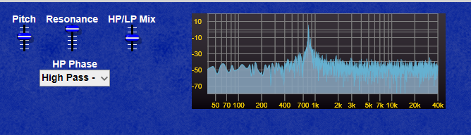
And in this example where the Low Pass is starting to predominate we get a notch with the resonant peak at a lower frequency.
High pass out of phase.
By inverting the high pass output, we can create a strong resonant peak when both High and Low pass signals are in balance, whereas in the previous example where the High pass was not inverted the output is almost flat when the two signals are in balance.
A state variable filter is a type of active filter in electronic circuits. It consists of one or more integrators, connected in some feedback configuration (there are a few different methods of feedback). It is essentially used when a precise Q factor is required, as other multi-order filters are unable to provide. There are various design methods used in analogue circuits (which I won’t go into here), but they all give more or less the same results.
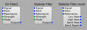
The choices of SV filter:
Note: State variable filters are all-pole filters, meaning they boost high frequencies even when the resonance value is low.
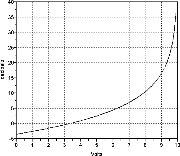
SV Filter2 – This one tends to be the one that has the most problems with overloading at high resonance levels. It has two “strengths” Single pole and Two Pole. In two pole mode the Low-pass and high-pass slopes are 12 dB per octave slopes, and band-pass or band stop (notch) modes’ slopes are 6 dB per octave. Also, the resonant response is nonlinear in the dB scale, as the graph below shows:
Around 10 volts, the resonance value skyrockets close to the point of self-oscillation. To prevent this, you may want to confine the resonance knob’s highest value to about 9 volts, or roughly 30 dB resonance. StateVar Filter – Much better behaved at higher resonance levels with the same switching between modes as the SV Filter2 StateVar Filter (Multi) – is essentially the same as the previous filter, but with separate outputs for Low, high, band pass and notch filter characteristics. This gives us all sorts of sonic possibilities by combining different filter outputs and mixing the levels. The four outputs will all change the signal’s phase in different ways, sometimes creating notches. Mixing Low Pass and High Pass outputs will create a band-reject filter. Negative voltages are perfectly acceptable on the Input2 plug of the Level Adj, so entering something like 10 for low pass and −10 volts for high pass means that the High pass level adj will invert the signal and subtract the high-pass from the low-pass output. This produces a flat response with a resonant peak at the cutoff frequency, which is great for adding resonant peaks to a signal. Note: State variable filters are all-pole filters, meaning they boost high frequencies even when the resonance value is low. This affects band-pass and high-pass outputs more than the low-pass output. And mixing these outputs adds a touch more gain. See the structure below for setting up a mixable SV Filter:
VA State Variable filters. These are the updated versions of the older filters listed above, and they do have an improved high frequency range, and better stability, but still need normalizing, and the Resonance limiting To 9V VA State Var VA State Var (Multi)
“Oberheim” style SV Filter
This filter takes the High and Low pass filter outputs and mixes them in variable amounts with the option to invert the phase at the output of the HP filter. This structure provides a wide range of sonic possibilities ranging through High pass, Low Pass, Bandpass, Notch, and resonance effects. The best way to find out what it’s capable of is to connect up a white noise source at the input, and have a listen (it’s also interesting to connect up the Frequency Analyser too) I found the best results were with the mix slider set with a range of 0 to 15V and a fixed value of 15V on the Level Adj in the Low Pass signal line.
Taming the SV filter.
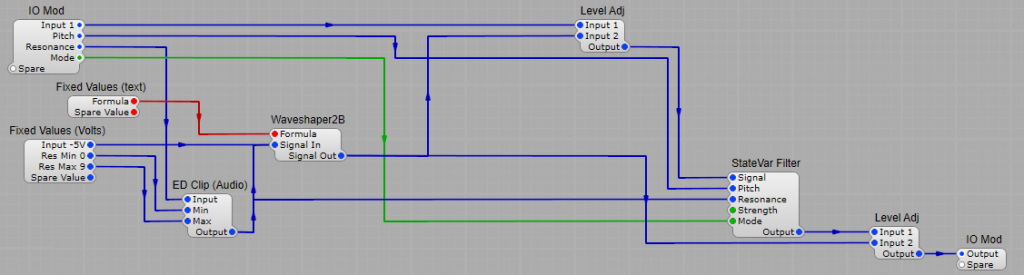
The SV filter is versatile, but at higher resonance levels, the gain can increase to the point of clipping, this is not good, because whilst it may sound fairly good when an analogue SV filter overloads, the Synthedit module will produce some really harsh distortion. Fortunately there is a way to tame this versatile filter, with Level Adj modules, and the Waveshaper. By taking the Resonance control voltage, by the way it’s always good to limit the rage of the resonance- I have done it here using an ED Clip (Audio) module to limit the resonance to 9V, rather than the maximum allowed of 10V. Too much resonance and the filter will self-oscillate and overload. By taking our resonance control voltage and feeding it through a waveshaper using a formula of 10-(x+5)x0.55 we can control the input and output gain in the Level Adj modules to get a fair approximation of constant signal levels at resonance settings between 0 and 9. This can be applied to all versions of the SV filter.
Note: Although the StateVar filters are better ‘behaved’ than the SV filter at higher resonance levels, adding this normalization to the filters is still worthwhile.
Credit: The Normalization structure is an adapted & updated version of the original from the book: Visual VST/i-Programming by H. G. Fortune (Editor), Peter Schoffhauzer, and David Haupt.
TD_Butterworth_HP Type: Butterworth high pass filter. Can be set from 2nd order filtering to 12th order filtering. There is no internal clipping on the kHz input voltage, and the control voltage only has the 1V/kHz characteristic.
TD_Butterworth_LP Type: Butterworth low pass filter. Can be set from 2nd order filtering to 12th order filtering. There is no internal clipping on the kHz input voltage, and the control voltage only has the 1V/kHz characteristic.
TD_P1Z1 Type: 1 Pole (6dB per octave), 1 Zero Filter. A specific design of Butterworth filter. Selectable filter modes: Low Pass, High Pass, Bandpass.
TD_P1Z1_ST Type:Stereo version of the 1 Pole (6dB per octave), 1 Zero Filter. A specific design of Butterworth filter. Selectable filter modes: Low Pass, High Pass, Bandpass.
State Variable Filters.
TD_SV2 Type: Linear State Variable Filter Filter Modes; Low pass 12dB per octave, High pass 12dB per octave, Bandpass 6dB per octave, Band reject 6dB per octave, Low pass 6dB per octave, High pass 6 dB per octave, All pass 12dB per octave.
TD_SV2_ST Type: Stereo Linear State Variable Filter Filter Modes; Low pass 12dB per octave, High pass 12dB per octave, Bandpass 6dB per octave, Band reject 6dB per octave, Low pass 6dB per octave, High pass 6 dB per octave, All pass 12dB per octave.
State Variable Formant filters.
TD_SVX4 Four zero peak gain state variable bandpass filters internally connected in parallel. Notes: Primarily designed as a building block for designers to create their own formant filters. Having a quad filter module uses less CPU than individual filters.
TD_SVX4_ST Stereo version. Four zero peak gain state variable bandpass filters internally connected in parallel.
Audio Crossover Filters.
TD_Xover12 Type: 12dB per octave crossover filter. This is module is built out of a standard State Variable filter and is suitable for modulation if need be
TD_Xover12_ST Stereo 12dB per octave crossover filter. This is module is built out of a standard State Variable filter and is suitable for modulation if need be.
Hilbert 90 degree filter network.
TD_Hilbert_A Type: Hilbert Filter network, this network creates 90 degrees phase difference between the two outputs. Notes: This uses an IIR 2 x 8 pole 90 degree phase-difference network. The outputs are approximately 90 degrees apart in phase, which is needed to build frequency shifters. The approximation in phase shift is not a problem for frequency shifting in general because if the input frequency shifts, so does it’s ability to cancel out with the original signal.
TD_Slew2 Control signal “slewer”. The type of slew can be set to; Constant rate, Constant time. Notes on Constant Time: It takes the same amount of time to go from 0-1 or 0-10. 1 volt = 1 second. The curve is exponential. Volts slew time is limited to a maximum of 20 seconds and a minimum of 1 millisecond. Notes on Constant Rate: It takes less time to go from 0-1 than 0-10, as it moves at the same speed between points. 1volt per 1second. The curve is linear. Volts slew rate is limited to a maximum of 20,000 volt per second and a minimum of 0.1 volt per second. Useful for introducing “glide/portamento” effects for control voltages, removing “stepper” effects, and smoothing out the output of sample/hold generators.
TD_PeakHold Type: Peak Hold Filter Notes: Generally used as a Peak hold for GUIs, and is not recommended for audio use. (You need to use a DSP-GUI bridge or Patch Mem)
TD_PeakHold Type: Stereo Peak Hold Filter Notes: Generally used as a Peak hold for GUIs, and is not recommended for audio use. (You need to use a DSP-GUI bridge or Patch Mem)
These filters are all suitable for use as a Voltage Controlled Filter (VCF) in synthesizers, and as such can have their cutoff and resonance frequencies modulated rapidly. Notes: It should be taken as read that all these filters have their control voltage internally limited to +10 Volts, and that they operate within the normalizer SynthEdit audio voltage range. Some may have the audio internally clipped so will distort at high input levels.
Ladder Filters.
TD_DiodeLP24_A Type: 24dB per Octave frequency roll-off diode ladder lowpass filter type A Notes: A simplified 4 pole diode-ladder lowpass filter with a single symmetrical non-linearity. Partial passband gain-loss compensation. Diode-ladder filters are unbuffered which leads to the cutoff frequency being a product of cutoff amount, input level and resonance.
TD_DiodeLP24_B Type: 24dB per Octave frequency roll-off diode ladder Lowpass Filter Type B Notes: A 4 pole diode-ladder lowpass filter, the first pole is an octave higher, with an additional unbuffered high pass filter in the feedback path that partially damps the resonance at low cut-off frequencies. An extra buffered high pass filter is on the input too. So it is more like a 5 pole + 1 pole filter. The filter cutoff slope is not a constant vs frequency. There are asymmetrical non-linearities, and partial passband gain-loss compensation. Diode-ladder filters are unbuffered which lead to the cutoff frequency being a product of cutoff amount, input level and resonance. Because of the first pole being an octave higher, maximum cutoff is 9.5 Octaves (~9.95kHz) if the sample rate is equal or less than 48kHz, 10.5 octaves (~19.9kHz) otherwise.
TD_DiodeLP24_C (EMS VCS3 Emulation) Type: 24dB per Octave frequency roll-off diode ladder Lowpass Filter Type C Notes: A 4 pole diode-ladder lowpass filter inspired by the paper “Efficient polynomial implementation of the EMS VCS3 filter” by Stefano Zambon and Federico Fontana. However it uses ‘Mystan’s Pivot’ method to approximate the non-linearities instead, which in this case are asymmetrical. Full passband gain-loss compensation. Diode-ladder filters are unbuffered which lead to the cutoff frequency being a product of cutoff amount, input level and resonance.
TD_Ladder5out_HP Type: Linear 4 pole High pass filter with five outputs Note: This module is useful as the basis for pole-mixing filters. Note: The filter does not self oscillate. Traditionally, 4-pole pole-mixing filters only mix the 4 poles. Two of the poles are inverting – either 1 and 3 or 2 and 4. Some short/set-high/bypass the first pole under some circumstances to get more variations. With this version, instead of bypassing – all you have to do is move the mixing-coefficients up i.e. hp1 coefficient, hp2 coefficient, hp3 coefficient becomes in-hp4 coefficient, hp1 coefficient, hp2 coefficient.
TD_Ladder5out_LP Type: Linear 4 pole Lowpass Filter with 5 outputs Notes: This module is useful as the basis for pole-mixing filters. Note: The filter does not self oscillate. Traditionally, 4-pole pole-mixing filters only mix the 4 poles. Two of the poles are inverting – either 1 and 3 or 2 and 4. Some short/set-high/bypass the first pole under some circumstances to get more variations. With this version, instead of bypassing – all you have to do is move the mixing-coefficients up i.e. lp1 coefficient, lp2 coefficient, lp3 coefficient becomes in-lp4 coefficient, lp1 coefficient, lp2 coefficient.
TD_LadderLP18_A Type: 18dB per Octave Transistor-Ladder Lowpass Filter Simplified filter version with a single symmetrical non-linearity. No passband gain-loss compensation. Self oscillates.
TD_LadderLP24_A Type: 24dB/Octave Transistor-Ladder Lowpass Filter Type A Simplified version with a single asymmetrical non-linearity. No passband gain-loss compensation (classic behaviour). Self oscillates.
TD_LadderLP24_B Type: 24dB per Octave Transistor-Ladder Lowpass Filter Type B Multiple asymmetrical non-linearities. Partial passband gain-loss compensation. Note: The filter does not self-oscillate.
TD_LadderLP24_C Type: 24dB/Octave Transistor-Ladder Lowpass Filter Type C This filter has a buffered high pass filter in the feedback path. This prevents self oscillation at very low frequencies and also prevents bass loss at high resonance levels. Asymmetrical non-linearities.
Oberheim X-Pander type filter.
TD_Panda (Inspired by the Oberheim X-Pander filter) Type: 4pole OTA Inspired Filter Notes: The filter poles are mixed internally to create 25 different frequency responses. Produces predominantly 3rd harmonic distortion. Self oscillates. List of Filter frequency responses; LP4, LP3, LP2, LP1, HP4, HP3, HP2, HP1, BP4, BP2, BPS, HP3LP1, HP2LP1, HP1LP3, HP1LP2, HP1BR2, BR2LP2, BR2LP1, BR4, BR2, BRBP2, LP1BR2HP1, LP1PK2, BR2PK2, HPX.
Sallen-Key filters.
TD_SK3P Type: Buffered 12dB/Octave Lowpass Sallen-Key Filter Frequency cutoff 12dB per octave slope. The extra pole is in the feedback path and limits resonance at higher frequencies and alters tracking a bit. Self-resonates up to about 3.7kHz. Symmetrical non-linearities.
TD_SK4P Type: 12dB/Octave Lowpass Sallen-Key Filter Experimental, has extra poles. Asymmetrical non-linearities.
TD_SK_A Type: Multi-Mode Sallen-Key Filter; Low Pass 12dB per Octave, High Pass 6dB per Octave, Band Pass 6dB per Oct. Buffered. This saves some CPU cycles compared to the Steiner modules. Asymmetrical non-linearity.
Steiner-Parker filters.
TD_Steiner_A Type: Buffered Steiner-Parker multi-mode filter Type A A Steiner-Parker filter is simply a multi-input Sallen-Key filter. Symmetrical non-linearities. Does not self-oscillate. Maximum input is +/- 10 volts. If the sample rate is less than, or equal to 48 kHz, then the maximum cutoff frequency is approximately 14 kHz otherwise it is approximately 19.9kHz.
TD_Steiner_B Type: Steiner-Parker Filter Type B An unbuffered version of a Steiner-Parker filter (the feedback loop is still buffered), which simply is a multi-input Sallen-Key filter. Asymmetrical non-linearities. Does not self-oscillate. Resonance decreases in higher octaves. Maximum input is +/- 10 volts. If the the sample rate is less or equal to 48kHz, maximum cutoff frequency is approximately 17.3 kHz otherwise it is approximately 19.9 kHz.
TD_Steiner_C Type: Steiner-Parker Filter Type C A buffered version of a Steiner-Parker filter, which simply is a multi-input Sallen-Key filter. Bright asymmetrical non-linearities. Self-oscillates. If the sample rate is less or equal to 48kHz, the maximum cutoff frequency is approximately 17.3kHz otherwise it is approximately 19.9kHz.
State-Variable filters.
TD_SV24_A Type: Cascaded State Variable Filters Type A; 24dB per Octave Low pass, 24dB per Octave High pass, and 12dB per Octave Band pass. Induced passband gain-loss to prevent too high levels with high resonance. This is a non-linear filter but it is not able to self-oscillate. This module uses less CPU than if two standard SE SV filters were cascaded.
TD_SV24_B Type: Cascaded State Variable Filters Type B; 24dB per Octave Low pass, 24dB per Octave High pass, 12dB per Octave Band pass. Induced passband gain-loss to prevent signal levels becoming too high with high levels of filter resonance. This is non-linear filter but it is not able to self-oscillate. The resonance level decreases as the filter cutoff frequency increases. This module uses less CPU than if two standard SE SV filters were cascaded.
TD_SV_C Type: State Variable Filter Type C; 12dB per Octave Low pass, 6dB per Octave Band pass. Experimental State Variable Filter that is modified by adding an extra feedback path around the structure, so it’s not really a true SV filter any more. Resonance decreases at higher frequencies. Asymmetrical non-linearities. Does not self oscillate.
TD_SVmo2 Type: Multiple Output State Variable Filter; 12dB/Octave Low pass, 6dB/Octave Band pass, 12dB/Octave High Pass The filter outputs can be mixed, combined or otherwise processed to achieve other filter shapes. Non-linear filter.
TD_SVmo2_ST Type: Stereo Multiple Output State Variable Filter 12dB/Octave Low pass, 6dB/Octave Band pass, 12dB/Octave High Pass The filter outputs can be mixed, combined or otherwise processed to achieve other filter shapes. Non-linear filter.
TD_SVxfade Type: Cross-fading State Variable Filter. Three pre-programmed selectable crossfade sequences. Select the filter type and cross-fade sequence from; Low pass /Band Reject /High pass, Low pass /Peak /High pass, Low pass /All pass /High pass. The cross-fade voltage range is from -5 Volts to +5 Volts.
So you decide you want to use a particular type of filter…lets say a State Variable, but it’s not quite right, you need a steeper filter roll off…what to do to fix this? Fortunately you can just add another SV filter in series with the first one, and this turns a 12dB octave low/high pass into a 24dB octave filter and the bandpass/notch into 12dB octave. So far so good, but there’s one very important thing to watch out for…the resonance settings on the filters. If we have both filters with adjustable resonance then as soon as we start to approach any moderate level of resonance the second filter will be heavily overloaded at some frequencies. To avoid this we can use the structure below, where the resonance of the first filter is fixed at 0.
Be careful when cascading SV filters. Cascading too many band-pass or high-pass outputs is not a good idea. It can cause annoying high-frequency ringing, because state variable filters boost high frequencies even at low resonance settings. Another catch with filters cascaded in series is they do introduce phase shift, so beware if you are intending to mix them with the “dry” audio signal, you’ll quite probably get some unwanted peaks and notches occurring due to phase addition and cancellation effects. You can see below that there’s clearly a change in phase between oscillator and the output of the second filter that changes with frequency.
Parallel Filtering.
This is a good way of achieving a stereo effect, especially using two different models of filter, as shown below with a Moog filter for the left hand channel, and the SV filter for the right hand channel. By having two independently controlled filters (albeit with a common Keyboard Tracking CV (KB Track) you can get a really rich stereo effect, (especially when the Pitch is modulated by out of phase LFO’s, but that’s another topic for later) Note: When constructing a layout like this inside a container (as is good practice) it’s a really good idea to follow these steps: 1) Set the filter Pitch plugs to 0V (they are pre-programmed at 5V) 2) Put both of the Pitch CV’s through their own Level Adj module with the Input 1 plug set to 0 volts (again they are pre-programmed to 5V), and the Input 2 Plug set to 10V. This prevents our container inheriting any voltages from either the Filters, or the Level Adj and setting them as an unwanted voltage on the KB Track IO Module, leaving you with an odd 5V offset appearing on another module’s control voltage. I spent quite a time at one point tracking down why the controls on one of my synthesizer modules were not behaving as expected-due to this inherited voltage from inside a container!
State Variable Multifilter.
A multi-filter takes things a step further. I won’t show the frequency spectrum for any of the settings because you’ll get a far better idea of the sounds it will produce by building one, hooking up a white noise source and having a listen. What we are doing is taking separate outputs from each part of the filter, then mixing them to achieve a sound we like. Of course if you want to get really complex you could have four individual SV filters with individually controlled frequency and resonance settings… the world’s your oyster (or mollusk of choice)here, feel free to experiment.
The Oberheim Xpander multi-filter.
Oberheim took the concept of the multi-filter and ran with it. The Voltage Controlled filter (VCF). The available modes on the filter are: a) One-, two-, three- and four-pole low pass b) One-, two and three-pole high pass c) Two- and four-pole band pass d) Two-pole notch e) Three-pole phase shift f) Two- and three-pole high pass plus one-pole low pass g) Two-pole notch plus one-pole low pass h) Three-pole phase shift plus one-pole low pass The output from this filter could the be mixed and routed in a variety of ways. TD Panda filter. The nearest ready made SynthEdit module to this is the TD_Panda filter module However all the mixing and levels are handled internally so while there’s a huge variety of modes for the filter you’re stuck with the internally set mixing.