Based on the Buchla Source of Uncertainty 266.
This module produces a random train of 100 mS long pulses, and a randomly varying control voltage, the minimum and maximum values of which van be varied.
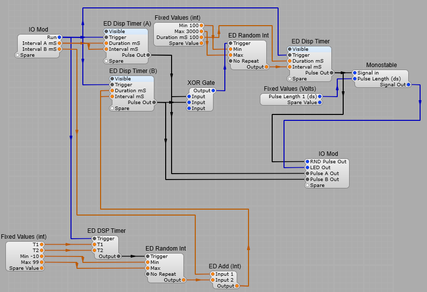
The Random Pulse Generator.
The principle of this module is that it produces two unsynchronized pulse trains running at different speeds. Pulse train B continually (1 second intervals) has a random value added to the Interval B mS setting by a an ED Random Int generator when the Module is triggered by a the ED DSP timer.
Pulse train A and pulse train B are fed into an X-OR gate. This produces a pulse whenever A or B is high, but not when both are high. The result of this is a pseudo random chain of pulses sent to the ED Random Int generator which outputs a new integer between 100 and 1000 each time it receives a Trigger pulse. The random integer is then fed to the Final ED DSP timer which is set to produce 100mS pulses with an interval set by the Random Integer.
This is fed to the RND Pulse out and a Monostable with the pulse Length set to 1 dS, this is used to flash an LED each time a pulse is output.
The structure of the Random Pulse Generator is shown below.
Note: This project relies heavily on Elena Novaretti’s module pack. The modules used in the project are;
ED Random Int,
ED DSP Timer,
ED Add Int,
ED Level Bar 2,
ED Random Volts,
ED Glider 2.
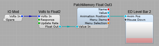
The Level Indicator.
This is just used as a visual indicator of the CV level being generated.
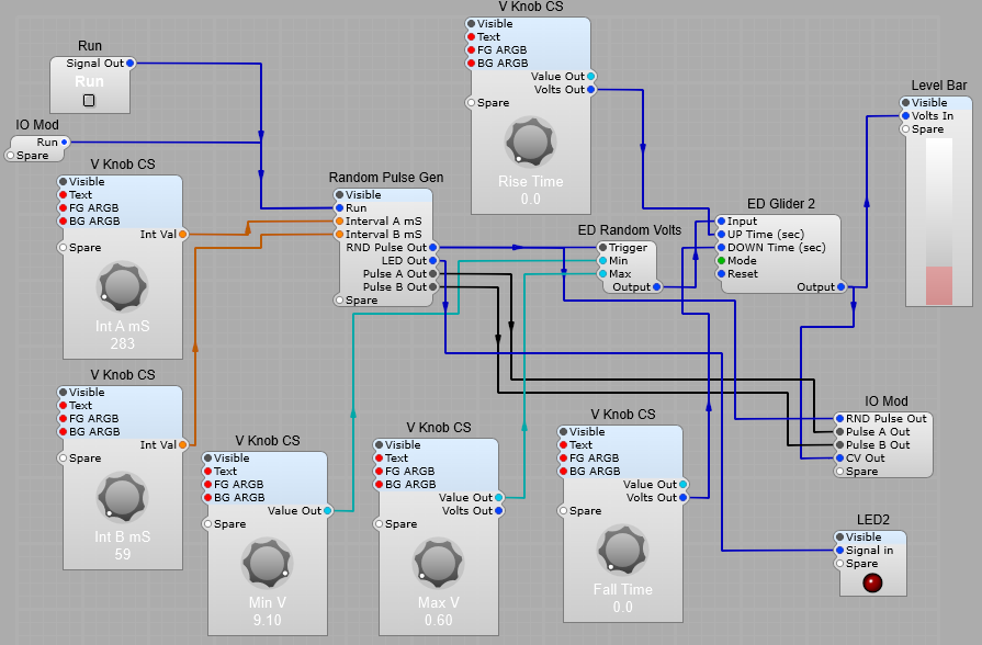
The Complete CV and Timing Randomizer.
The RND Pulse out is fed into the ED Random Volts module. Each time this is triggered a new voltage is randomly generated. The Minimum and Maximum range of the output voltage is set bu the Min and Max knobs. The output voltage is fed to the ED Glider module. This module allows the rise and fall times to be set. The Glider mode should be set to constant time.