Patch leads and Plugs are colour coded depending on the signal type.
Plugs (AKA Pins) are the coloured ‘spots’ on the modules, and Patch leads are the cables we “draw” to connect the modules.
The text, and coloured spot on each module represents a plug that can be used to connect to other modules using patch cords.
A plug allows parameters of the module to be changed using the output of another module, such as a control, information to be transferred, control voltages, to be sent and received and
Input plugs are normally located on the left of a module, and output plugs are on the right of a module.
There are a few exceptions to this rule in the range of GUI modules
Plugs are colour coded depending on their signal type, as are the patch cords.
DSP versus GUI data.
This is the section that contains some of the controls for the DSP modules, and the interface/control panel itself, GUI handles all the key clicks, mouse events
So you can see what type a module is the DSP modules are grey, and the GUI modules are blue.
In general you are not able to connect GUI to DSP directly, but there are some modules that allow information to pass between GUI and DSP modules. GUI/DSP Converters are part Light Blue part Light Grey.
DSP or Digital Signal Processing.
This covers Oscillators, Filters, Modulators, Inverters, Level control, Voltage controlled amplifiers, and the controls such as knobs, lists, sliders, lamps and switches. These are the modules that generate, control, and process your sounds. Most controls send voltages to the modules, but some such a list entry, allow you to select one value out of a pre defined list in a module. There are some with values you can pre-set such as Boolean (0 or 1), Voltage,
DSP versus GUI Data.
DSP data cannot be directly connected to a GUI module due to the different ways of handling data. Synthedit will not allow the direct connection. The data speeds are higher for DSP reflecting the amount of data which must be processed, and GUI data rates are lower to allow more CPU priority to be given to the DSP signal handling.
You must use a special data conversion module to communicate between the two types of data, and never use this to process DSP data, the conversion should only be used to send signals from a GUI control to a DSP module to change it’s operating parameters. Never try and use GUI to DSP for modulation or other rapid changes.
Timing.
In Synthedit communications between DSP and GUI is meant to be accurate enough to handle controls and visual display items. There is no guarantee of precision accuracy.
This means that for for fast timing and data updates there is a risk that data will be skipped or mis-timed. For this reason (and others) you should never convert DSP data to GUI to use GUI modules to process DSP signals. Not ever.
DSP Sample rate data is at 44 kHz or more while GUI communication takes place at roughly 30 to 60 Hz!
In short do not try and use GUI modules to handle DSP data. It will fail.
Bit Depth
SynthEdit processes all signals internally at 32 bits floating point.
When SynthEdit write to files it outputs either 16 bit integer, or 32 bit floating point samples.
Sample Rate
Many software synths separate control signals and audio signals. Control signals e.g. LFO’s and Envelopes are processed at a low sample rate, this saves on CPU power, but results in sluggish envelopes and zipper noise (noticeable stepping clicks on fast envelopes, panning or volume fades). You also have the hassle of having conversion modules.
To maintain sound quality, SynthEdit uses the same high sample rate for all audio signals. As a result SynthEdit just sounds cleaner and more responsive than many other soft synths. SynthEdit supports any sample-rate. The Oscillator waveforms are generated at run time to suit the sample-rate.
The types of data signals.
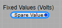
Blue:- Normal Audio or Control Voltage signal. DSP use only.
Audio, or control voltage signals. Voltage is essentially floating point data. It is used to send Audio from one DSP module to another, or to send control voltages from one DSP module to another to control the recipients behaviour.
DSP Floating Point and Volts pins will inter-connect. Connecting a Float output plug to a Volts input plug should cause no problems, because smoothing of the Float value will take place automatically. However it’s not good practice to connect a Volts output plug to a Float input plug, as many of the Float inputs on a DSP module are not intended for use with fast changing modulation values and making this type of connection can cause crackling and audio dropouts when modulating the value on the plug.
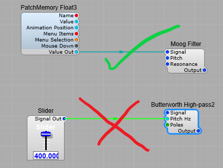
Note: Voltage plugs are always DSP Plugs.
—————————————————————————————————-
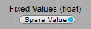
Light Blue:- Floating point values
A floating point number, is a positive or negative whole number with a decimal point. For example, 5.5, 0.25, and -103.342 are all floating point numbers, while 91, and 0 are not. Floating point numbers get their name from the way the decimal point can “float” to any position necessary within the number.
Note: With large numbers, there are times when maths results from floating point calculations are not 100% accurate.
—————————————————————————————————-
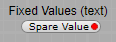
Red:- Text data.
The Text data type stores any kind of text data. It can contain both single-byte and multibyte characters that the locale supports. The term simple large object refers to an instance of a Text or Byte data type.
Text can be GUI or DSP.
—————————————————————————————————-
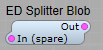
BLOB:- Binary Large OBject.
This is a more technical aspect of data in Synthedit, and is not often used except in passing large amounts of binary data in or between modules when using or creating samplers, or sample players.
In Synthedit it has a built in limit of 5MB. trying to pass more than 5MB of data won’t work that amount of data can’t be handled and will just be dropped (ignored) and not transmitted.
A “BLOB” is a common acronym for “Binary Large OBject”, which means it’s a data object holding a large amount of binary data. Some languages have native BLOB types, but C++ doesn’t. Never the less, creating a blob is simple enough – you just create an array of bytes. This is done by creating an array of characters. This might be confusing, though, as an array of characters has a special meaning in C++ – it’s also a string.
For more information you really need to read in depth C++ programming tutorials and documentation.
—————————————————————————————————-
Orange:- Integer/ Integer64.
The Integer data type stores whole numbers that range from -2,147,483,647 to 2,147,483,647 for 9 or 10 digits of precision.
Note:- The number 2,147,483,648 is a reserved value and cannot be used. An Integer value is stored as a signed binary integer and is typically used to store counts, quantities, and so on.

—————————————————————————————————-
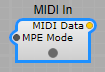
Yellow:- MIDI data.
MIDI is an acronym that stands for Musical Instrument Digital Interface. It’s a way to connect devices that make and control sound — such as synthesizers, samplers, and computers — so that they can communicate with each other, using MIDI messages.
Synthedit takes the MIDI input from your chosen device, and converts it into control signals (voltages) that it’s modules can understand to control the modules actions.
—————————————————————————————————-
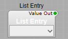
Green:- A list of values. For example, Waveform names. DSP Only. Usually connects to a drop-down list.
—————————————————————————————————-
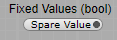
Black:- Boolean (logic on/off). This (for those of you familiar with electronics) is like the system used by TTL and CMOS logic chips.
—————————————————————————————————-
NOTE: SynthEdit will not allow you to connect patch cords to plugs of a different signal type without using a converter except for Voltage and Float (But you should always use a data type converter).


