Stuck with a SynthEdit project?

Tag: Delay effects

An improved Reverb design in Synthedit .

Third Party modules.

Requires the TD Allpass Dly2 module.

Using a single Delay2 for a very basic reverb effect is all well and good, but has its limitations, one of which is that at the short delay times we are using there can be noticeable peaks and troughs in the frequency response, as what we are setting up is basically a comb filter, so we can get some ringing effects on transients at certain frequencies, and also a “drainpipe” like effect on other sounds. Not good. So what’s the answer?

The Schroeder Model of Reverb.

If we put a sharp transient sound such as a handclap into a delay line then
exponentially decaying impulses follow the first impulse. Though this
is similar to an exponentially decaying reverb, in the frequency
response peaks occur at equally spaced frequencies like the teeth of a
comb, hence the name comb filter.

How sound decays (fades away) in a room or hall.

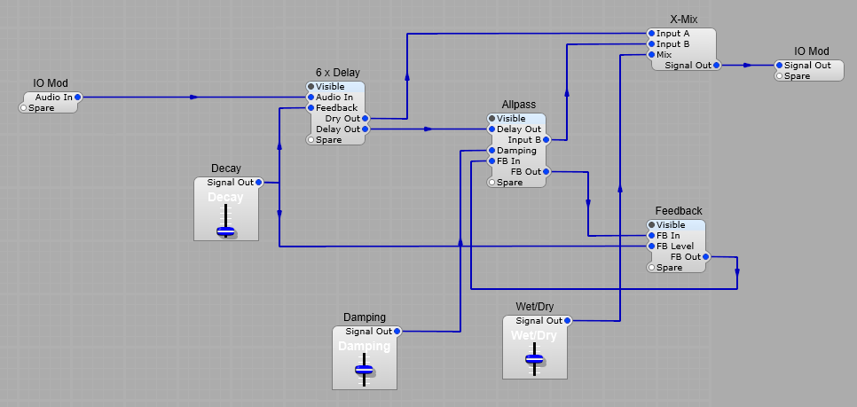
This will result in a ringing metallic sound, especially once feedback is added into the mix. Digital audio pioneer Manfred Schroeder proposed using parallel delays with differing delay times, in combination with all-pass filters for digital reverb. His idea proposed a structure with four parallel delays and two serial all-pass filters. The delays create the reflections, and the all-pass filters “smear” any transients thus making the reverb more diffuse and reducing any resonances. Schroeder’s design is shown below in block form. Each comb is a Delay2 module.

Block diagram of the Schroeder type reverb

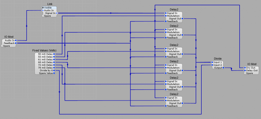
6 x Delay container:
A set of six Delay2 modules pre-set to differing delay times within the range of 10 to 60 mS which is the ideal range for reverb, any longer and we start to get an echo effect, and shorter and there’s no noticeable reverb effect.
All the outputs from the Delay2 modules are fed into the Input 1 of a Divide module, this is because if we just feed all the signals into a normal module they will all be added together, more than likely exceeding the input range of the module causing clipping. Input 2 of the divide module is set to 6 (the number of delay modules) to restore the normal signal range. There have been various calculations made for the “ideal” delay times, but in practice a natural reverb depends on the shape and size of the area, and the things in that area.
There has been a calculation made of the “ideal” delay times which are
50, 53, 61, 68, 72, and 78 ms
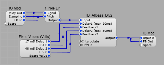
All Pass Container:
The All Pass container uses two more Delay two modules in series one set to 17mS, and another to 74mS these two delays give an added “blurring” effect to any transients, along with a 1pole Low Pass filter for variable HF damping on the reverb “tail”
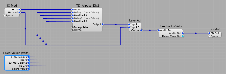
All pass section

Feedback Container:
The feedback container has a Feedback – Volts module to allow feedback. A combination of the inherent time delay in a feedback loop in SynthEdit, and the two All Pass filter modules adds further frequency dependant phase shifting to further reduce ringing and metallic sounding transients. Again the frequencies of the All Pass filters are fairly random, but spaced out to try and give maximum effectiveness in reducing unwanted audio artefacts.

The feedback section

Creating a very basic Reverb effect in Synthedit with the Delay2 Module.

BBD Reverbs.
First there were plate and spring line reverbs, then along came an electronic “chip” called a Bucket Brigade Delay (BBD). This used high impedance CMOS devices and capacitors to pass the electric charge (audio) along the line, each stage in the line adding a small delay. These worked well, and eliminated the problems of external noise entering the signal chain. However the way they worked introduced their own artefacts such as aliasing at high frequencies, filtering was used filtering to restrict this, and they also introduced a certain amount of distortion, which gave them their own unique low-fi sound. By using multiple chips with different delay times you could get some quite complex reverbs.

Delay2.

Creates a delay (echo or reverb) effect on audio signals very similar to BBD chips.
Note: If you intend to modulate the delay time, you should enable interpolation, this reduces clicks and “zipper” noise.

The SynthEdit Delay2 module

Plugs.
Left Hand Side:
Signal In:- (Voltage) Input Signal
Modulation:- (Voltage) Varies the delay time dynamically (0 to 10V)
Feedback:- (Voltage) Controls the amount of feedback of the delayed signal.

Right Hand Side:
Signal Out: – (Voltage) Audio output signal
Parameters:
Delay Time (secs): – Maximum delay time in Seconds. The delay time is limited to a maximum of 10 seconds.
Interpolate Output: – Provides smoother modulation of delay time, but with an increase in CPU load.

Basis BBD style, single delay reverb effect.
We can emulate this in a SynthEdit module, which takes the audio input, and much like the old BBD chips, slices up the audio into samples and passes them down the delay line.
Shown below is our very basic reverb effect.
Delay Time:- Set the delay time to 0.001 Seconds (10mS) in properties
Delay control:– Set the maximum voltage for the delay slider to 0.06 volts, this gives us a delay time range of 10mS to 70mS.
Feedback:– Set the maximum voltage for the Feedback slider to 8 volts, as we don’t want the absolute maximum feedback level as it will just give uncontrolled oscillation.
Wet/Dry:- This control will default to a range of -5 volts to +5 volts. Leave this as it is to give the full range of wet to dry effect.

Very basic reverb structure

There’s one important point to note, if this reverb is being included as part of a Synthesizer VST we need to think about polyphony. It really isn’t needed for a reverb effect so we need to containerise our reverb, put a Voice Combiner module in place in the input- the voice combiner forces then the Modules in this container to stay Monophonic. Otherwise every time you play more than one note on your Synth plug in it will create an un-necessary clone of the reverb module wasting CPU and memory.

Optimising CPU with your reverb

Making the Reverb Stereo.

Stereo Reverb

Converting to Stereo is easy, we just create two identical Reverb chains, one for the left channel, and one for the right channel. Keep the two delay and feedback levels linked otherwise some very peculiar (and unwanted) phase and stereo imaging effects can be introduced.

Limitations of basic Delay reverbs.

This is structure is OK for a very basic reverb effect, but has its limitations, one of which is that at the short delay times we are using there can be noticeable peaks and troughs in the frequency response, as what we are setting up is basically a comb filter, so we can get some ringing effects on transients at certain frequencies, and also a “drainpipe” like effect on other sounds. Not so good. So what’s the answer?
Fortunately there is one that was devised by Manfred Schroeder, known as the Schroeder Model of reverb.

Creating a Flanger effect in SynthEdit.

What is a Flanger?

The term Flanger was coined sometime in the mid 20th century, It was discovered when two tape machines played the same signal at the same time. The story is that a recording engineer placed a finger on a tape reel’s flange, slowing one tape and throwing the two out of sync. When the engineer released the reel, its speed gradually returned to normal, giving a psychedelic whoosh. The origins of the term “Flanger” has various explanations…
How a Flanger works.
Flanging is an audio effect produced by mixing two identical signals together, one of the signals is delayed by a small and gradually changing period, usually between 5, and 20 milliseconds. This produces a swept comb filter effect: peaks and notches are produced in the resulting frequency spectrum, related to each other in a linear harmonic series.

Comb filter spectrum

Varying the time delay causes these to sweep up and down the frequency spectrum. A Flanger is an effects unit that creates this effect. Part of the output signal is usually fed back to the input (a “re-circulating delay line”), producing a resonance effect which further enhances the intensity of the peaks and troughs. The phase of the fed-back signal is sometimes inverted, producing another variation on the Flanger sound, the phase inversion causes peaks in the frequency response instead of notches (see the red line in the chart below).

How Positive and negative feedback affects the spectrum

As you can see Flanging differs from phasing in a notable way: A phaser generally has one notch frequency, whereas a Flanger has a number of harmonically related notch frequencies giving a comb like spectrum.

Creating a basic Flanger in SynthEdit.

The easiest way is to use a Delay2 module. Below is the structure of a simple Flanger. I find it’s best to keep the Mod depth’s maximum value to about 9 Volts as the full 10 Volts can sometimes produce some odd artefacts over 9.5 volts, we do this by setting the maximum value of the Mod Depth Slider control to 9 Volts.. The offset 5V is to keep the delay time in the centre of the useful delay time “window”.
Note: When constructing a Flanger in SE you should check the Interpolate box in the properties panel for the Delay2 module, and make sure it’s ticked. This greatly reduces any “stepping” or “zipper” effects in the audio when we are modulating the Delay2 module.

Basic Flanger

Adding an external Feedback loop with switchable phase.
With a few extra modules, we can create an external feedback circuit to give you a choice of negative or positive feedback loop for the Flanger.
Normally feedback loops are not allowed in SynthEdit, but if we add a special Feedback module we can have feedback. It does however introduce a delay of approximately 2mS into the loop however, which will affect the response of the filter above 2 kHz. See the structure below for the layout (the Feedback – Audio Module is actually Feedback – Volts Module, but in this context I think saying audio makes much more sense). The Phase Inverter is the standard Inverter2 Module, which just inverts the polarity of the audio, which is in effect a 180 degree phase change. The Feedback amp is a standard Level Adj Module and we use a Switch (1->Many) with a List Entry Module to switch from 0 degrees feedback to 180 degree phase shifted feedback. The feedback plug in this structure is not connected, and can be set at 0 Volts in the properties panel, or if you wish you can use a Fixed Value (Volts) module to hold the feedback level at 0 Volts.

Flanger with external feedback and phase switching.

Improving the SynthEdit Flanger.
Flangers may often produce a loud low frequency hum at high feedback levels. By adding a high-pass filter after the delay line we can fix this
problem.

Adding a High Pass filter in the output.
Here I have used two single pole filters to give a reasonable 12dB/Octave cut-off slope. You could have a fixed filter frequency, but I have used a slider control to allow a little manual control between 50 and 800Hz. To do this set both the 1 Pole HP filters Frequency Scales to 1V/kHz in the properties panel, and then set the Slider control’s Minimum to 0.05 Volts and the Maximum to 0.8 Volts.
There is a reason for this variable high pass filter, often we can improve the clarity of the Flanged signal by cutting out low frequencies so it’s nice to be able to control the cut-off frequency, and it can also remove some low frequency aliasing by-products.

Flanger with Phase switching and a High Pass Filter.

Making a stereo Flanger in SynthEdit.

Its quite a simple job to convert the simple Flanger to stereo.
We just need to add an extra input and output channel, so we have left and right sides, then copy parts of the basic Flanger setup: see below.
A nice touch is to change the LFO to the TD_LFO_B_ST module.
This is a “Stereo” version of the LFO we used previously, with two outputs instead of one, these outputs are also adjustable in terms of their phase relative to each other, so we could set our Left hand Flanger channel sweep voltage to be 180 degrees out of phase with the Right hand channel. Having the two channels sweeping differently will give us not only a more complex flanging effect, but also an interesting psych-acoustic panning effect too due to the phase and time differences between the two channels.

Stereo flanger