The problem with Patch Points.
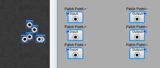
The existing Patch Point modules are fine, but a little basic. If you’re setting up a panel with a large number of patches you need to be very disciplined about labelling and arranging them. As I have found it’s too easy to get in a muddle. As you see below we can start with a nicely laid out pattern of patch points, switch to the panel view…and it’s chaos, and you have to select ech one, then switch to panel view and arrange everything. With some labelling the problem is solved, you can just arrange your panel view in one go.
Making life easier.
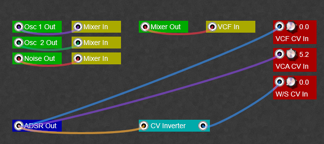
What would help is a text label and maybe some colour coding. We can do this fairly easily with a few sub controls. With a little planning we can produce a Patch Bay something like this… even having a few useful things like gain controls and inverters in the patch bay.
Note: I’m sorry but the colours are limited to the patch points, there’s no way round this until Jeff introduces (please, please do this Jeff) colour customizable patch leads for the Patch Points. Also the transparency can’t be altered either. Patch cables are only fully visible when you hover the mouse over the patch point.
Note: You can plug more than one cable into a Patch Point.
Note: To disconnect a cable, right click on the Patch Point itself.
How the patch points are customized.
Not much to say about this really, this is just to point you in the direction of your own style of Patch Points and patch bay.
Note: Do pay attention to the Z-order of the modules, otherwise you can end up with a hidden lable or Patch Point! From top layer down you want this order;
1) Patch Point
2) Text
3) The rectangle.
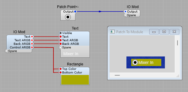
A Patch Point for connection to the Output of a module.
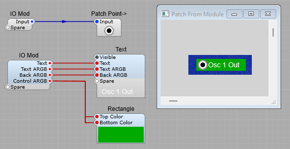
The plugs on the prefab are for controlling the appearance. (Apart from the input/output signals of course).
Text: The is the lable next to the patch point
Text ARGB: the ARGB colour settings for the label text
Back ARGB: The ARGB Colour settings for the background of the text. You’ll most likely want to leave this as 00000000 (Transparent background)
Control ARGB: The ARGB colour settings for the Rectangle used as the Patch Point background. Note: If you want rounded corners just go into the properties settings on the panel and adjust them.
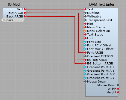
Inside the Text container.
This is containerized just to make the structure on this article a little easier to read
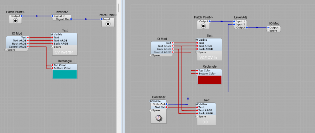
A Patch point for connection to the input of a module.
An Inverter patch point, and a gain control patch point.
Just for ideas, really all sorts of patch points are possible from now on.
Leave a Reply