About the DAM Kinetic Engine LTE.
This is a module for using a kinetic motion emulator to produce two varying control voltages, similar to the KAOSS bad on Korg KAOSS synthesizers.
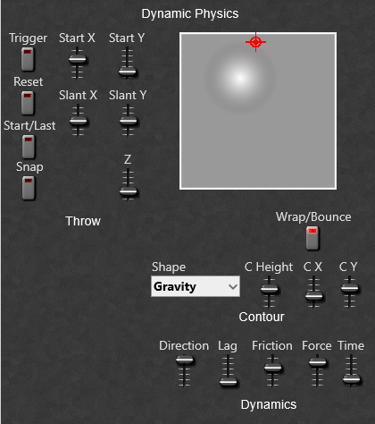
The basic idea is of using a ball rolling on a surface, the shape of which can be controlled. The shape of the surface has either a positive hump (hill), or a negative hump (depression) which will affect the motion of the ball. The ball can be started with a trigger button, a clock pulse, or by triggering from a MIDI input.
Note: Using a MIDI trigger makes the module Polyphonic unless a Polyphony module is used to make the structure Monophonic.
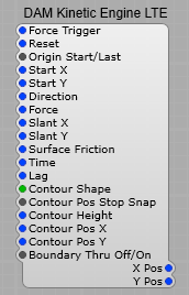
The Kinetic Engine module and its plugs.
Left Hand Side Plugs:
Force Trigger:- This triggers a new throw of the Kinetic motion ball. Can be connected to the Trigger out of a MIDI-CV 2 module, or to momentary button. When connected to the MIDI-CV 2 module the module is Polyphonic, and will create a new ball for each note played.
Reset:- Resets the module to it’s current control settings.
Origin Start/Last:- Select whether the Ball is thrown from it’s current position, or from the position set by the Start X and Start Y controls.
Start X:– Value 0 to 1 V. Sets the start position of the ball, 0 being the Left Hand border of the surface, and 1 the Right Hand border.
Start Y:– Value 0 to 1 V. Sets the start position of the ball, 0 being the bottom border of the surface, and 1 the top border.
Direction:– Value 0 to 10 V. Sets the direction in which the ball if pushed along the surface.
Force:- How hard the ball is pushed in the direction of travel.
Slant X:- Value 0 to 10V. Tilts the plane of the surface on the X axis.
Slant Y:- Value 0 to 10V. Tilts the plane of the surface on the Y axis.
Surface Friction:- Value 0 to 10VCoefficient of Friction of the surface (how much it slows the ball down over time).
Time:- Value 0 to 10V. Slow down or speed up time (the rate at which everything interacts).
Lag:- Value 0 to 10V. Controls how “sharply” the ball bounces off a boundary. The more lag the more the ball curves.
Contour Shape:- -10 V to 10V. Controls the slope of the “hump” from the edges to the centre point. Negative values are a dip, and positive are a peak. Some contour examples are;
1) Gravity- The closer to the centre the greater the attraction or repulsion,
2) Linear- Constant slope,
3) Shallow- Steep at the edges and gentle in the centre,
4) Steep- Gentle until the ball reaches the centre where the slope markedly increases. There are more shapes to try, experimentation is the key.
Contour Pos Snap:-
Contour Height:- Value -10 to +10 V. Controls the height of the hump, or depth of the depression.
Contour Pos X:- Value -1 to +1. Position of the Hump/Depression on the X axis.
Contour Pos Y:- Value -1 to +1. Position of the Hump/Depression on the Y axis.
Boundary Thru Off/On:- Turns on and off the boundary (walls) when on the ball bounces off the wall, when off the ball wraps to the opposite boundary.
Note: All the parameters are designed to be voltage modulated from an LFO or random voltage source, but do remember the parameter ranges.
Right hand side plugs:
X Pos:- Range 0 to 1 Volt. The output control voltage relative to the position of the ball on the X axis.
Y Pos:- Range 0 to 1 Volt. The output control voltage relative to the position of the ball on the Y axis.
Using the Module.
This makes an ideal way to demo the module and get a feel for how it reacts to the various settings and the various contours.
IMPORTANT NOTE: Make sure all the containers used have their properties set to “Visible”, and “Controls on Module” for the Structure/Prefab to work Correctly.
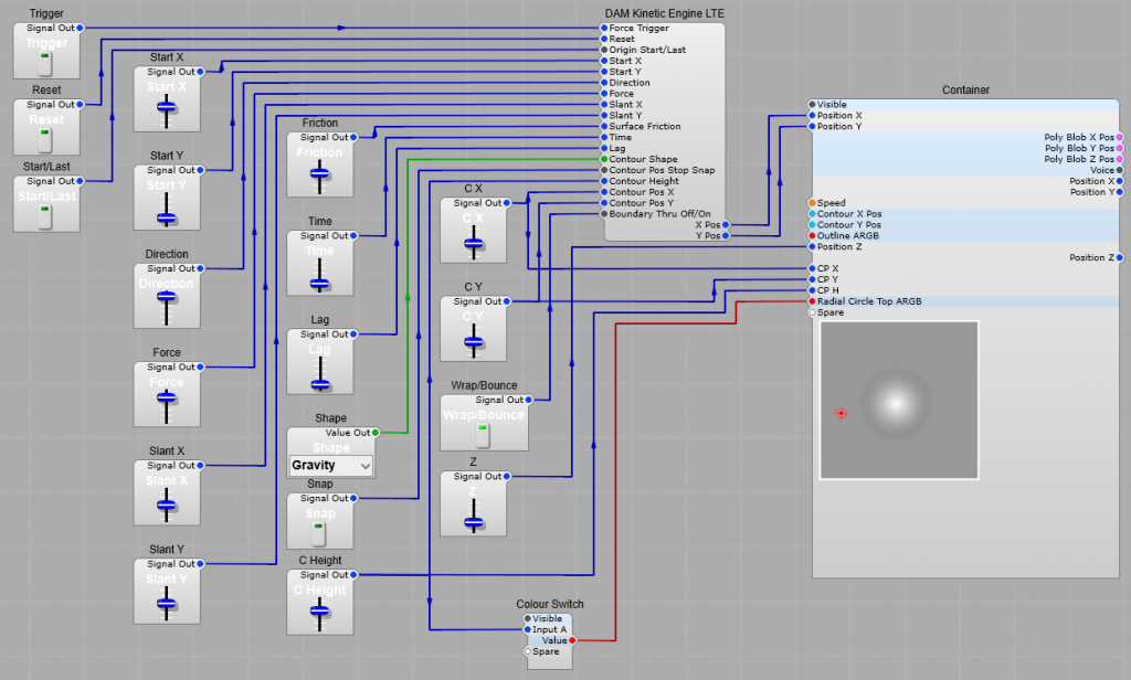
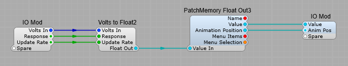
The Volts 2 GUI Float prefab.
Nothing special about the converters for the “Bump” X and Y position converters.
Kinetics Display.
This consists of a DAM Poly Capture XYZ, and a DAM Poly Render to convert the X and Y voltages to the display format. A DAM Rectangle is used to add a border representing the boundary, and a visual representation of the “hump” in the surface and its position. The ED GUI Multiply float modules are used to correctly scale the Radial Circle values for display. (As shown added to the module names in brackets i.e. (300)).
Note: the following settings in properties are required. Make sure that the radial circle is ON, and the Radial Circle Bottom is set to 00 (Transparent). Set the outline to ON, and to your chosen colour.

Set the Top and Bottom ARGB for your required background colour for the Kinetics pad.

The complete Kinetics display structure is shown below. Position Z sets the size of the ring around the Kinetics Ball.
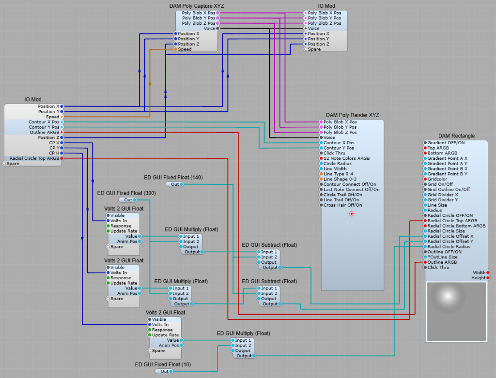
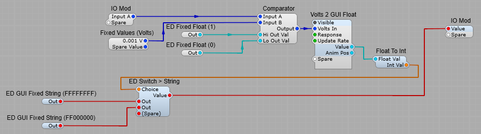
Switching the “Bump” colour.
With this String switch prefab we can change the “bump” from white (positive values), to black (negative values). The comparator switches between high, and low, which sends a 0 or 1 to the switch to change the Radial Circle Top colour from Black to White as required.
It actually switches at 0.001 V (1mV) which is close enough to make little difference.
The finished Kinetic Engine prefab in action.
Leave a Reply