Stuck with a SynthEdit project?

Category: Waveshaper

Using Waveshapers.

In electronic music, waveshaping is a type of distortion synthesis in which complex spectra are produced from simple tones by altering the shape of the waveforms.

Uses

Waveshapers are used mainly by electronic musicians to achieve an extra-abrasive sound. This effect is most used to enhance the sound of a music synthesizer by altering the waveform.
The simplest form of Waveshaper could be considered to be the Rock guitarist’s faithful effects pedal, the “Fuzz box”. Some synthesizers or virtual software instruments have built-in Waveshapers. The effect can range from subtle “warmer” sounds through added harmonics, overdriven “Fuzz” sounds, and metallic inharmonic sounds. The end result can bear no resemblance to the original sound fed into the shaper

How it works

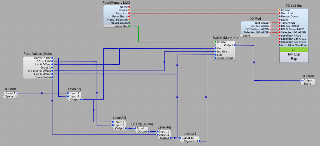
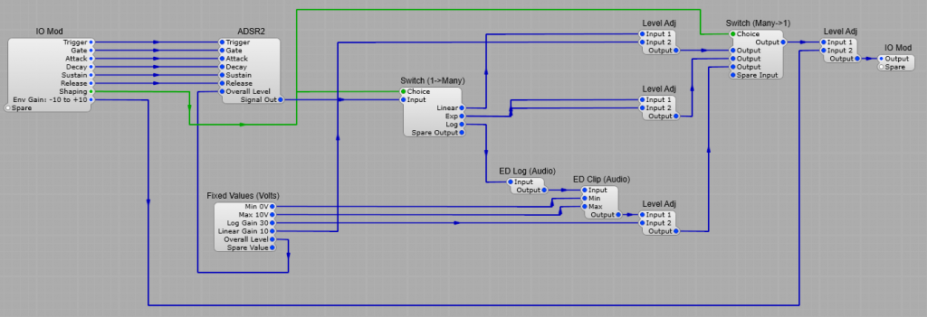
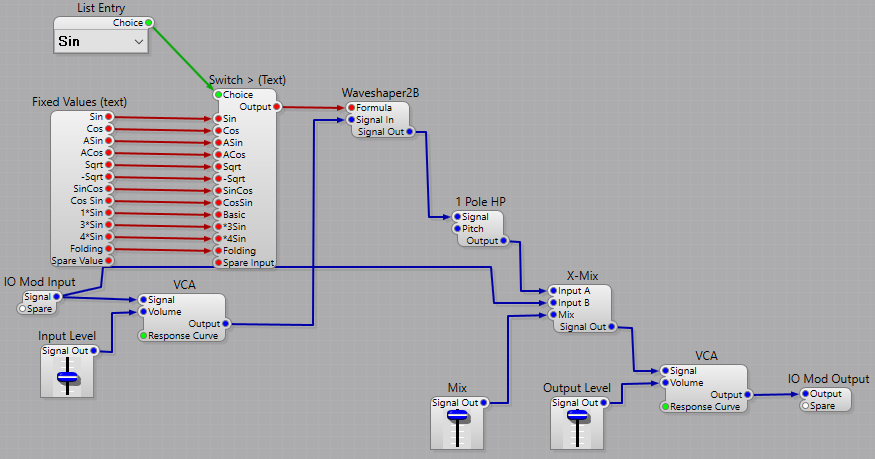
A waveshaper is an audio effect that changes an audio signal by mapping an input signal to the output signal by applying a fixed mathematical function, called the shaping function. The Harmonic or Inharmonic content of the signal is entirely dependent of the shaping function. In SynthEdit we can’t control any of the parameters by voltage control, it’s all done by a fixed formula supplied as a text string.
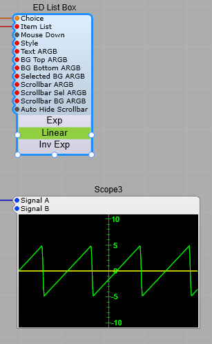
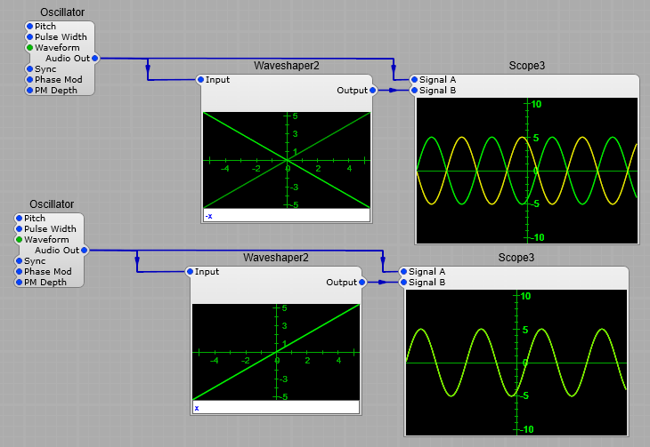
Consider the diagram below.
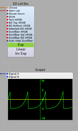
In the top example, we have a function where the output is identical to the input. This is due to the fact that our function x results in -1=-1 and +1 =+1, so the transfer is not altering the signal.
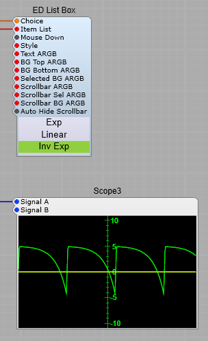
In the bottom example our function of -x results in -1=+1 and +1=-1 so we have inverted the sine wave input. There will be no noticeable harmonic change, just a polarity inversion.

Changing the formula from x to -x

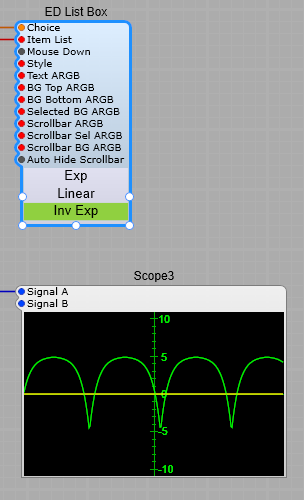
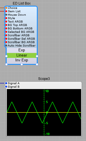
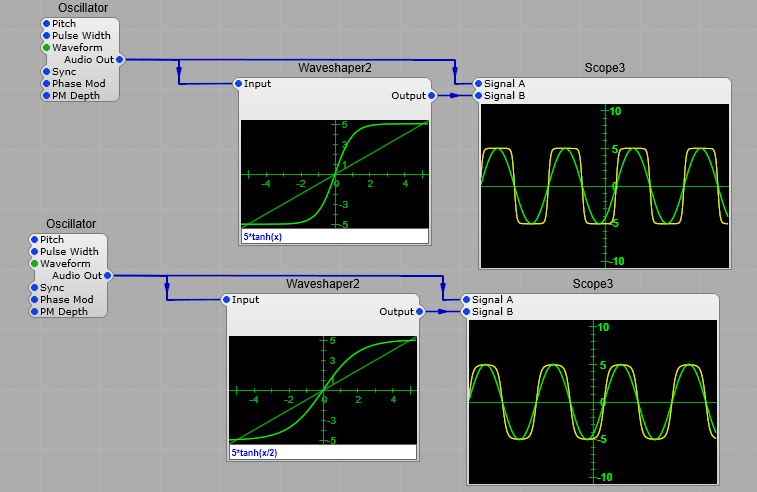
Soft clipping example using 5*tanh(x)

Our next example below is entirely different. As you can see changing the transfer “curve” results in an entirely different output. Here we have used the function of 5*tanh(x), which “soft” clips the sine wave input.
There is one important point to note here when using the waveshaper: that is that it has a maximum input of +/- 5 volts if we exceed this it will clip the input regardless of what formula you are using.

By changing our formula from 5*tanh(x), to 5*tanh(x/2), we don’t affect the level of the signal, but we do soften the clipping effect even more. (Try 5*tanh(x*2) if you want slightly harsher clipping.

In general the steeper the transfer curve the more harmonics you will generate.

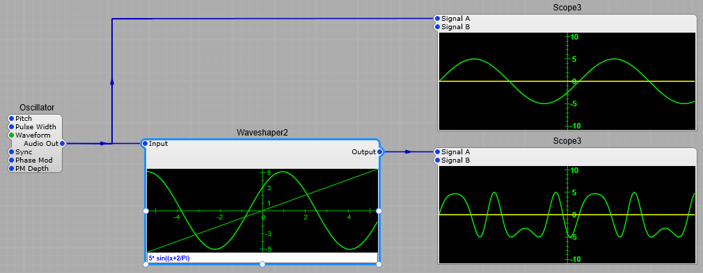
Note: All the examples shown below have a pure sine wave input.

5*tanh(x)

Formula: 5*sin(x+2/PI)

5*sin(x+2/PI)

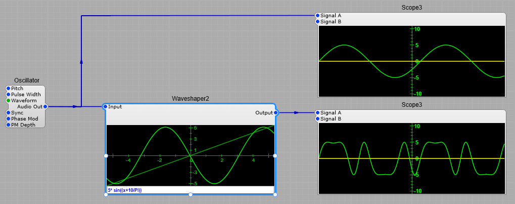
Formula: 5*sin(x+10/PI)

5*sin(x+10/PI)

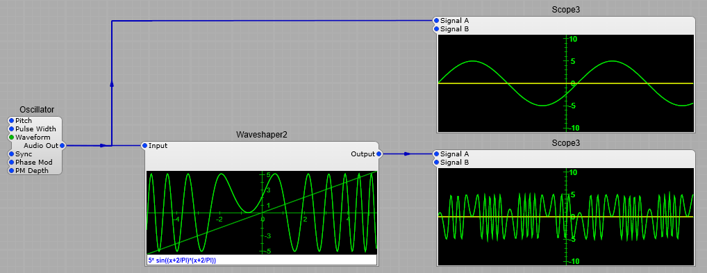
Formula: 5*sin((x+2/PI)*(x+2/PI))

5*sin((x+2/PI)*(x+2/PI))

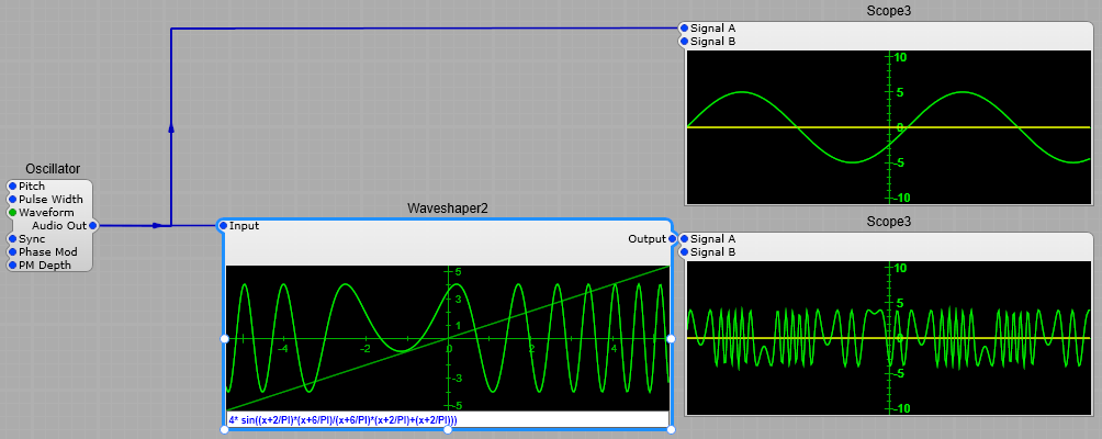
Formula: 4* sin((x+2/PI)(x+6/PI)/(x+6/PI)(x+2/PI)+(x+2/PI))

4* sin((x+2/PI)(x+6/PI)/(x+6/PI)(x+2/PI)+(x+2/PI))

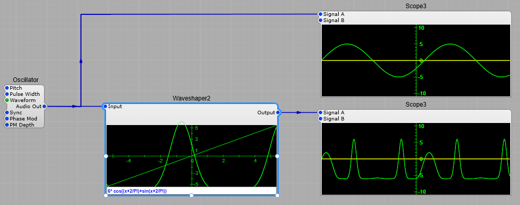
Formula: 6* cos((x+2/PI)+sin(x+2/PI))

6* cos((x+2/PI)+sin(x+2/PI))

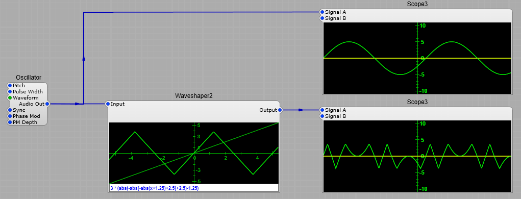
Formula: 3 * (abs(-abs(-abs(x+1.25)+2.5)+2.5)-1.25)

3 * (abs(-abs(-abs(x+1.25)+2.5)+2.5)-1.25)

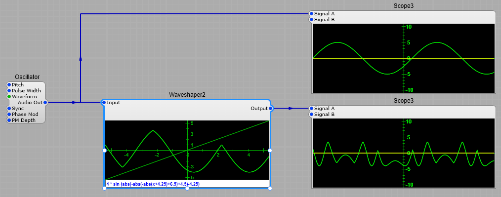
Formula: 4 * sin (abs(-abs(-abs(x+4.25)+6.5)+4.5)-4.25)

4 * sin (abs(-abs(-abs(x+4.25)+6.5)+4.5)-4.25)

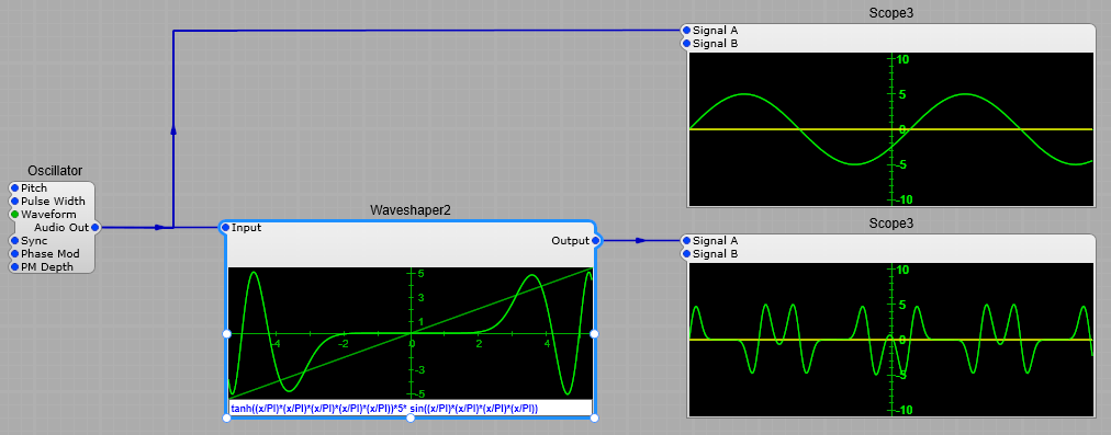
Formula: tanh((x/PI)(x/PI)(x/PI)(x/PI)(x/PI))5* sin((x/PI)(x/PI)(x/PI)*(x/PI))

tanh((x/PI)(x/PI)(x/PI)(x/PI)(x/PI))5* sin((x/PI)(x/PI)(x/PI)*(x/PI))

As you can see there are some quite interesting effects to be had from a waveshaper. Experimentation (and a some mathematical knowledge) is the key to getting usable results.

Note about Input voltages:
You really need to keep both the input voltage under control, and the curve in the waveshaper screen.
Once the input goes outside +/- 5V you will get digital clipping, and aliasing.
If the input is going outside this range use a level adjust module.

Important note:
When putting you formula together be sure to use brackets, and make sure you close them when needed- one missed bracket will destroy your carefully crafted formula.

Note about formulae, and keeping the voltages under control:

You need to keep the output from the waveshaper under control to avoid clipping in modules further down the chain. Once again it will be digital clipping, and that’s not pleasant. To demonstrate if we use the formula
tanh((x/PI)(x/PI)(x/PI)(x/PI)(x/PI))5* sin((x/PI)(x/PI)(x/PI)*(x/PI)) and alter it to
3 * tanh((x/PI)(x/PI)(x/PI)(x/PI)(x/PI))5 sin((x/PI)(x/PI)(x/PI)*(x/PI)) the whole thing starts to go badly astray…

3 * tanh((x/PI)(x/PI)(x/PI)(x/PI)(x/PI))5* sin((x/PI)(x/PI)(x/PI)*(x/PI))

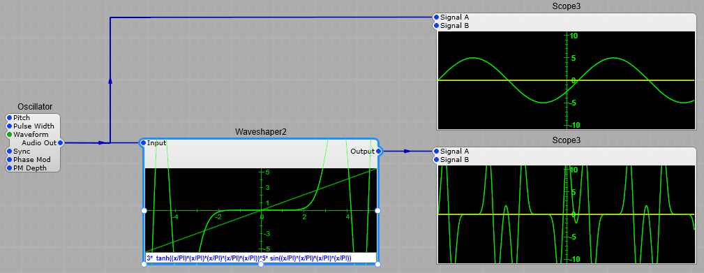
You can see that the curve on the module is going well outside the limits, and that the output is well over +/- 10 V, so any modules after this will be overloaded.
If this does happen then just modify the formula values, or if that doesn’t help you can do the following:
tanh((x/PI)(x/PI)(x/PI)(x/PI)(x/PI))5* sin((x/PI)(x/PI)(x/PI)*(x/PI))/2

tanh((x/PI)(x/PI)(x/PI)(x/PI)(x/PI))5* sin((x/PI)(x/PI)(x/PI)*(x/PI))/2.

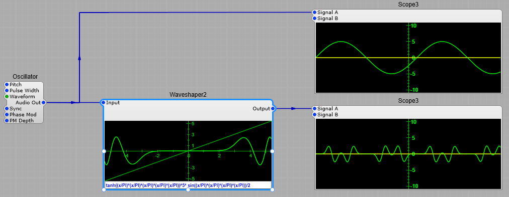
Adding the /2 at the end of the formula has reduced the level by half.
To sum up:
If the output is too low multiply the whole formula by a suitable number, if it’s too high divide the whole formula by a suitable number.
A good investment if you want to get serious about devising your own formulae would be a set of Trigonometry tables, Log and Exponential tables, a good scientific calculator. A book on mathematics and Trigonometry would give a few insights too.
Wildly devising a formula without any planning and “hoping for the best” really won’t work (except by pure luck).

Linear to Log/Exp conversion for LFO & ADSR.

Converting an LFO Waveform.

This circuit converts a normal Ramp/Sawtooth input with the default range of +/-5Volts, to an exponential Ramp/Sawtooth. Any offset or gain voltages are shown on the fixed value modules. This module works well with an LFO but as it stands is not suitable for use with an ADSR as it works in the -5 to + 5 V range , and not the 0 to 10V range of an ADSR.

Shown below are examples of the output waveforms. It is useful with Sine, Saw, Ramp and Triangle waveforms but not Pulse. I have used offset voltage rather than a DC blocker HP Filter on the output to make the voltages symmetrical about the 0 Volt (Y) axis, as the High Pass filter would affect the waveshape changing our LFO output once again.
Important Note: Any gain control MUST be placed preceding this module so as not to change the symmetry of the waveform around the 0 Volts axis.

Exponential Saw
Exponential Triangle, Inverted exponential Triangle, linear triangle
Inverted exponential saw, Exponential saw, linear saw,

Converting an ADSR Envelope.

This is slightly more complicated as we are dealing with the range of 0 to 10 Volts so we need to do some clipping to make sure the lowest output voltage is 0 Volts and to increase the output of the ED Log so we get the full 10 V range.
For this reason the Overall Level plug on the ADSR 2 module must be fixed at 10. The gain adjustment is made at the output of the prefab so we can go between -10 for inverted envelope and +10 for full normal envelope. Generating the exponential envelope just needs a Level Adjust module with the envelope feeding into both inputs.
Note: The sustain levels will be different between Linear, Exponential and Log shaping – as yet I haven’t found a way to avoid this issue. Blame the laws of mathematics!

Using the ED Sine Shaper

Basic overview of the module.
This module is a fully modulatable (up to and including audible frequency modulation) mathematical waveshaper, using a natural Sine function.
Harmonically rich and interesting sounds can be obtained shaping a plain sine wave oscillator with this module.
The Sine accuracy can be selected with the hidden Accurate pin (exact Sine vs. cubic approximation, about half CPU load).
Note: The audible difference is often negligible though.

Plugs:
Input: The audio signal to be modulated.
Sine Frequency: The Sine Frequency plug specifies the sine frequency as the amount of complete cycles per 10 V of input signal. For those who are interested the formula is: V_Out = sin(V_In * Freq * 2PI / 10)
Output: The audio output resulting from the audio input being acted upon by the Sine frequency function. Note: this can reach +/- 10V peak to peak, so will need attenuating in most usage.

Demo structure.

The easiest way to demonstrate this module is with the setup below, where we can have an sine wave audio oscillator feeding the input, and another oscillator set up to run at lower frequencies. If we use a ramp waveform running at about 0.5 Hz we can clearly hear the effect as the effect of the Sine Modulation value fading away. It sounds a bit like a filter which is almost on the point of self oscillation being swept through its cutoff range, but without any filtering effect.
The best way to learn how it sounds is experiment.
The only point of note is the +5 V offset on Input 1 of the Level Adj module, this is to keep the modulation voltage positive at all times.
Note: The one oscillator waveform that doesn’t really work either as source or modulation is noise… this just results in slightly distorted noise!

Creating a Voltage Controlled Waveshaper in SynthEdit.

Having some control over the waveshaper (although not over the actual transfer curve in the module) is possible in as far as the depth of the shaping effect, and the polarity of the shaping effect can be voltage controlled using a few stock modules, and one extra from Elena Novaretti’s module packs at www.elenadesign.eu, the ED Range Clipper which limits the amount by which the control voltages can be varied- this is used to prevent the control voltage exceeding the normal range for the waveshaper and causing unpredictable results.
The Intensity (or depth) of the effect can be varied between 0 V (minimum shaping) and 10 V (maximum shaping). This is then fed to the X-Mix module directly to Input B, and through an Inverter2 module to Input A. This allows us to effectively change the polarity of the waveform, which is then added to the Input audio at the final Level Adj module.
Of course you’re not limited to just using the Waveshaper3 module, you could just as easily use the Waveshaper2 module and use a formula for the transfer curve.

Voltage controlled waveshaper diagram

So far this is the best I have been able to come up with, but I’m as always going to keep experimenting so “watch this space” for updates on this technique

DH-Wshape2 Third party waveshaper module.

Hands up all those who love the sound of “Digital” Synthesizers? If you do then one of this module is for you. Especially if you want to be able to control the amount of Waveshaping by using a control voltage.
It’s a “Third Party” module courtesy of RH Modules http://www.rhmodules.nl/downloads/dspgui/
The basics are quite straightforward. The ‘Scope and 1kHz Oscillator modules are included just to show the effect of the DH-Waveshaper. The default for the Shape control voltage is +/- 5 Volts, but this can be increased to +/- 20 Volts to give a wider range of shapes. See the screenshots below…
The only waveforms that aren’t worth putting through the waveshaper are a pulse (you’ll get some wild amplitude changes and some very large spikes on the leading and trailing edges), or noise. Unlike the SynthEdit stock Waveshapers there are no formulae to set up, just a control voltage

The effect of +20 Volts Shape CV
This gives and extreme foldback effect on the positive and negative peaks of the audio input.

Output of the waveshaper with +20V gain CV

The effect of 0Volts Shape CV
Here we get a slight flattening of the sine wave peaks which gives a very subtle distortion, almost like a slightly overdriven valve PA.

Output of the waveshaper with 0V gain CV

The effect of -5 Volts Shape CV
This gives us a “crossover distortion” effect where the audio input doesn’t start to appear at the output a until the audio input has risen slightly above 0 volts.

Output of the waveshaper with -5V gain CV

The effect of -20 Volts Shape CV.
Starts folding back the 0 volts crossover portion of the audio input.

Output of the waveshaper with -20V gain CV

Modulating with an ADSR module.
Just as a basic “bare bones” idea of what’s possible, you could have the waveshaper modulated by an ADSR2 triggered by the keyboard so the peak level of the audio is the most distorted.

Control the waveshaper with an ADSR module

Modulating with an LFO Module.
Or a free running LFO so that the distortion varies slowly (or rapidly) over time

Control the waveshaper with a LFO module

SynthEdit Waveshaper2b

This one is available in both SynthEdit V1.4 and V1.5
However there is a GUI module you can use to display the transfer curve from your formula which is only available in V1.5.

Waveshaper 2B in SynthEdit 1.4

This gives us a text box for entering our formula, with no means of displaying the Transfer Function curve.

Waveshaper2B in SynthEdit 1.4

Waveshaper 2B in SynthEdit 1.5

Whereas in V1.5 we have an additional module Waveshaper 2B GUI, which allows us to display the curve. Now the only real difference between Waveshaper 2 and 2B is that we can have a separate text box for entering our formula which can be resized for longer formulae, and by using a third party Text Entry module (such as the ED or DAM modules) can be customized to give control over font and background colours.

Waveshaper2B in SynthEdit 1.5

So with a little work we can have a demo that shows the input signal, the formula, which can be edited, the resulting curve, and the resulting output waveform.

Waveshaper2B demo in Syn
thEdit 1.5
Panel view of the Waveshaper demo

A SynthEdit Waveshaper Prefab.

This design uses some pre-defined mathematical functions to shape the input waveform. The Formulae for the shaping are all held in a Fixed Values (Text) module from where they can be selected.
These values are sent to a Switch > Text module. From there they are fed to the Waveshaper2B module where the mathematical function is applied to the input waveform. The 1 Pole HP filter is to block any DC component that the Waveshaper might introduce. From there the X-Mix module sets the balance between the unaltered input, and the shaped signal.

Notes:
All the Slider controls are left at their default values.
Formula 12 (Folding) is purely a foldback distortion, the Sin and Cos formulae add some 2nd/3rd/4th harmonics giving a formant like sound to a sine or triangle input.
Using Sqrt (Square Root) formulae can give some quite spiky waveforms.
Formulas used:
1) Sin: 6sin((x+2/PI)+(x+2/PI))
2) Cos: 5cos((x+5/PI)+(x+5/PI)) 3) ASin 2asin((x/PI)+(x/PI))
4) Acos: 2acos((x/PI)+(x/PI)) 5) Sqrt 5 sqrt((x/PI)+(x/PI))
5) Sqrt: 5*sqrt((x/PI)+(x/PI))
6) -Sqrt: -5*sqrt((x/PI)+(x/PI))
7) Sin Cos: 6*sin((x+2/PI)+cos(x+2/PI))
8) Cos Sin: 6*cos((x+2/PI)+sin(x+2/PI))
9) Default: 5*sin(x/PI)
10) 3*Sin: 6*sin((x+2/PI)+(x+2/PI)+(x+2/PI))
11) 4*Sin 6*sin((x+2/PI)+(x+2/PI)+(x+2/PI)+(x+2/PI))
12) Folding: 3 *(abs(-abs(-abs(x+1.25)+2.5)+2.5)-1.25)
Other functions can be used, although some may result in outputs with a very high amplitude, or nothing at all, feel free to experiment.

Structure of the waveshaper prefab

Adding a Butterworth High Pass filter will also greatly reduce any unwanted low frequency “rumbles” which can be introduced.
As you can see in the Frequency Spectrums below the layout with the Butterworth High Pass filter in circuit, a lot of the “noise” below 200Hz is drastically reduced. The filter was set to a cut-off frequency of 200Hz, and the number of filter Poles to 12.

Adding a better high pass filter to the prefab

Unfiltered output:

Filtered output (about 200Hz High-Pass):

SynthEdit Waveshaper 3

This is a purely graphical waveshaper. It’s still a DSP module, so there is no need for any conversion between GUI and DSP data.
Although there is the Waveshaper2 or 2B, if you’re not mathematically inclined, or want to allow your plugin users to change the waveshaper’s function then this is by far the easiest solution. It’s very intuitive, you just click on a node (one of the small green squares) and drag it till you get the result you want. You can see below how dragging the nodes changes the output waveform.

Effect of moving nodes on the transfer curve

You just need to be aware that moving the centre node (0,0) can cause some issues with clicking and unwanted DC offset voltages (for audio you could put a high-pass filter set to about 50Hz cut-off pitch to filter out the DC component), when dealing with LFO’s or modulation envelopes you really do want to avoid moving the 0,0 node.
Another advantage is that as your plug-in users are unable to enter values into the waveshaper, they can’t cause the output to exceed the default +/- 5 Volts for Audio voltages.
The best way to learn this module is to connect it up and try dragging the nodes to see what the result is.

A test setup for the Waveshaper 3 module

SynthEdit Waveshaper 2

A Wave-Shaper distorts or modifies the input voltage depending on the transfer function that you specify. They can be used as a distortion unit, soft clipper, waveform modifier or control voltage transfer function (e.g. velocity response curve), they are to say the least, versatile.

Waveshaping is also a popular synthesis technique that turns simple sounds such as a sine wave into more harmonically complex sounds.
A guitar fuzz box is an example of a very basic waveshaper. The unamplified electric guitar sound is fairly close to a sine wave. But the fuzz box works by amplifying it to the point where the input clips the peaks of the signal in an amplifier designed to clip at moderate signal levels. A signal that is clipped has many more high frequency harmonics added to its spectrum. Sounds that have passed through any type of waveshaper will have a lot more high frequency harmonics, which gives them a “richer” sound.

Table based Waveshaping.

As you can probably imagine doing all these calculations in real time at audio frequencies is going to be a lot of work for the computer. So we generally pre-calculate these polynomials and put the results in a table. Then when we are Waveshaping sounds, we just take the value of the audio input and use it to look up the answer in the table. In the world of computer programming this is called optimization, and it greatly reduces the load on your CPU.
One big advantage of using a table is that regardless of how complex the original equations were, it always takes the same amount of time to look up the answer. You can even draw a function by hand without using an equation and use that hand-drawn function as your transfer function.

The SynthEdit Waveshaper2 module.

A simple waveshaper transfer function

The Waveshaper 2 module is just an in-out module, where you specify the transfer function either in the text box on the module, or in the module’s properties panel. Changing the formula will also change the curve in display that represents the transfer function

Changing the waveshaper transfer function formula-the effect

Note:
Input Levels: The input voltage is internally clipped at +/- 5 Volts, while it won’t do any harm to exceed these values, the results won’t bear any relation to the expected results from the formula.
Output Levels: These may be higher or lower than the default SynthEdit level of +/- 5 Volts depending on the transfer function specified. We can adjust the formula to compensate for this, we just change the multiplier at the beginning of the transfer function (shown in bold): Output = 5*sin(x/PI)

A simple Waveshaping Formula.

A waveshaper in DSP form can be described as a function that takes the original input signal x, and applies a mathematical formula to the input thus producing a new output signal y. This function is called the transfer function. A simple example in SynthEdit is shown below:

Showing the effect of the Waveshaper basic formula on a sine wave

Here we use a simple equation: Output = 5*sin(x/PI), the important part (the transfer function) is shown in bold. we merely multiply the results of the transfer function by 5 to restore the output to its normal SynthEdit +/- 5 volts peak to peak audio level.
In order to change the shape of the function (and not just make it bigger or smaller), the function must be nonlinear, which means it has exponents greater than 1, or functions (this is where we use sines, cosines, exponentials, logarithms, etc.). You can use almost any function you want as a waveshaper. But the most useful ones output zero when the input is zero (that’s because you usually don’t want any output when there is no input-this will result in unwanted clicking noises).

Showing the effect of changing the Waveshaper formula to 5 * sin((x*1.2)/PI)

If we change the equation slightly to: 5 * sin((x*1.2)/PI) the bold section is the change we insert, then the output goes from having the peaks flattened out, to a small amount of foldback, the greater the number we use to multiply x, the greater the waveform is folded back on itself- see below where it’s increased to x*1.8

Showing how the formula affects the Waveshaper output

Increasing the Input voltage:
What happens if we exceed the usual SynthEdit audio levels? Well with the most basic function we used in the first example you might possibly think you’ll get a result like we had in the last example where it starts to fold back, but it doesn’t it just goes into “hard clipping”. To demonstrate I put an amplifier between the signal source and the waveshaper with a gain of *3- you can see the result below.

Increasing the input above +/- 5V does not produce the expected results from the Waveshaper

And if we take the function that gave us the foldback:- 5 * sin((x*1.8)/PI),
and increase the input above the default level, then the following happens:

Increasing the waveshaper input above +/- 5V does produce some strange results

The reason for this is that the input of the Waveshaper modules in SynthEdit is internally limited to the default of 10 volts peak to peak, so when we reach the clipping voltage the waveform loses its sine wave like shape and is clipped. So to ensure correct operation we need to ensure that the input never exceeds +/-5 Volts (especially when using external audio sources). Likewise the result of the function must be scaled correctly to restore the default output of+/- 5 Volts audio that SynthEdit uses.

Need to convert a Sine wave to a Square wave?
Then this formula will do the job for you: 5*sgn(x/pi)

Converting a sine wave to a square wave with the Waveshaper

If we want to “pull” a sine wave into more pronounced peaks the following formula works well: 0.15 * sinh(x/1.2)

Producing a more exponential transfer curve from the waveshaper

Which also has a useful effect on Sawtooth and Triangle waves, so you can see how this can also be useful for manipulating envelopes and control voltages provided we pay close attention to the input and output voltage swings.

Effect of the new curve on a sawtooth
Effect of the new curve on a triangle wave