Creating a multi stage Stereo Phaser with a Resonator.
You’ll need third party modules for this project.
I used these modules created by Davidson;
DAM List Block Grid
DAM V Knob
These modules by Elena Novaretti;
ED GUI Divide (Float)
ED GUI Add (Float)
ED GUI Line 3
ED GUI Fixed Value (Float)
This TD Module;
TD SV24B (You could use the Stock SV Filter, but I don’t think it sounds quite the same)
This QTN Module;
QTN VoltToGUI (Float)
Left and Right Phaser container.
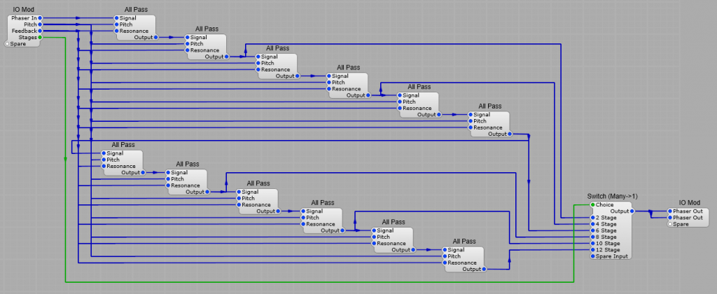
Multi-Stage All-Pass filter
This although looking complex is actually twelve All Pass Filter modules in series, with the outputs of modules 2, 4, 6, 8, 10, and 12 connected to a Switch (Many > 1) allowing the selection of how many filters are in the chain. The control voltages are used on all the Filters, and only the first All Pass Filter is routed to the input IO module.
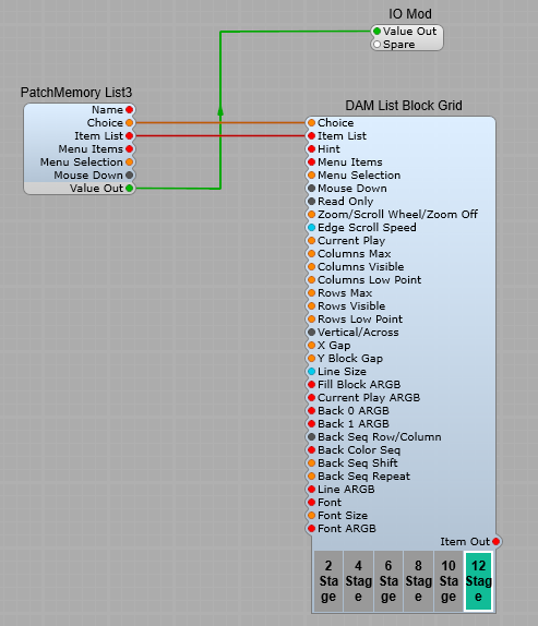
Stage Selector.
Here I have used a 3rd party module, Davidson’s DAM List Block Grid (you could substitute the stock list entry module but I personally think this looks better.
It’s connected to the PatchMemory List3 module to convert to the green list plug.
As with any list all the values will be automatically read from the module it’s connected to.
Settings.
The only settings I have changed on the Block List grid are;
Columns Max = 6,
Columns Visible = 6,
Rows Max = 1,
Rows Visible = 1.
To adjust the height and width of the Block Grid, open the panel view, select the grid and drag the borders to the required size.
Note: I will be doing a separate post on all the features and settings of this module in the near future.
The DAM List Block grid is also used in the same manner for the +ve/-ve audio switch, just change the columns to 2, and the rows to 1.
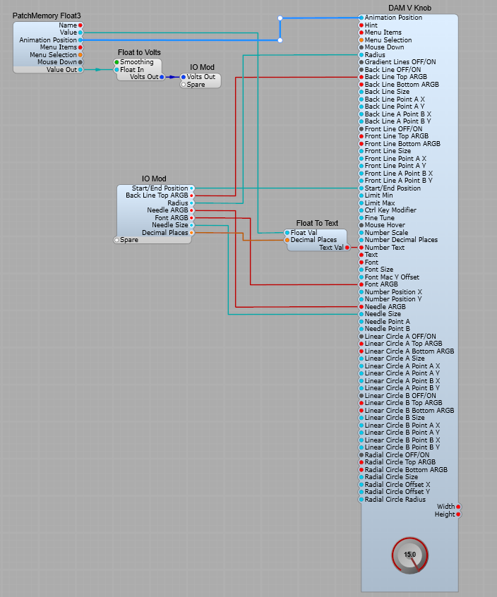
The control knobs.
This is another one of Davidsons 3rd party modules. This one has the advantage that it can be customized, and even better resized unlike the stock Knob control.
As with the stock Image2 module when using it for a control knob, the Animation position is fed through a PatchMemory Float3, and a Float to Volts module to provide the DSP voltage output. As per usual the range of the control is set from the Min/Max setting of the PatchMemory
Settings.
The only settings I have changed on the DAM V Knob are;
Radius = 70 This can be adjusted to suit your GUI. It controls the total radius of the control knob,
Back Line Top ARGB = FF880000 This is the colour of the line on the outer rim of the control that follows the needle,
Start/End position = 30 as this makes the knob behave more like a traditional control knob. This controls the start and end positions of the controls rotation,
Number Display (In the module properties panel drop down list) Change this to “Number Text”
Font ARGB = FF000000 you can change this to your own choice of colour, this is the number displayed in the centre of the control.
Needle ARGB = FF880000 to match the Back Line colour.
Needle Size = 0.6
Note: I will be doing a separate post on all the features and settings of DAM V Knob module in the near future.
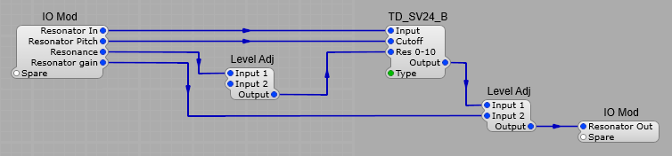
Resonator.
The resonator is a TD_SV24_B filter module set to BP 12 module. There is a Level Adj module on the Res 0-10 input with it’s Input 2 plug set to a value of 9V so that the filter stays just below the point of self-oscillation. The filter type is set to BP12.
The Level Adj module in the output controls the amount of signal from the Resonator reaching the output mix.
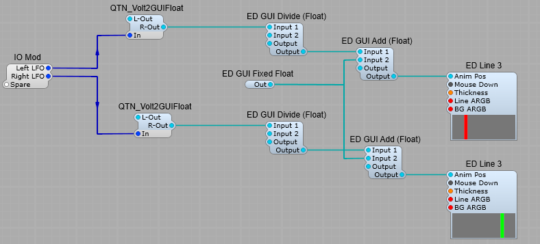
Phase Indicator.
This is linked to the outputs of the Left and Right LFO outputs to give a visual indication of the phase difference between the two outputs.
This relies completely on third party modules.
The QTN_Volt2GUIFloat take the DSP input voltage and convert it to GUI Float, which is then fed into the ED GUI Divide (Float) module where we divide by 10 (Put a value of 10 on Input 2), and add 0.5 on Input 2 of the ED GUI Add (Float) module where it is then fed to the ED Line 3 module. I changed the thickness setting to 5, and the Line and Background ARGB settings to give red and green for the two channels, on a dark grey background
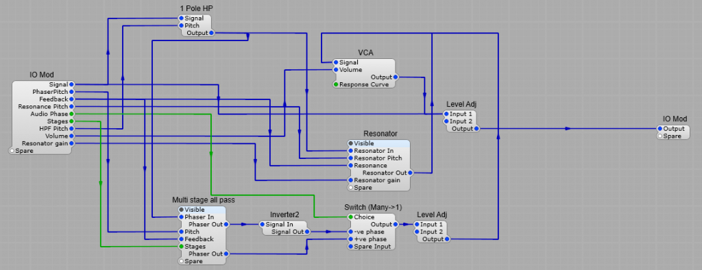
The complete Phaser
The LFO is a TD_LFO__ST with Phase control on the Right channel, and the LFO Type set to TriSaw. A good range for the LFO Hz control is 0.01 to 5.
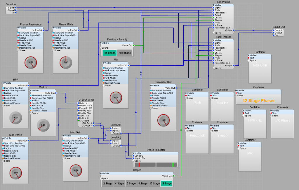
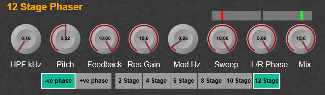
The Phaser control panel