How to create a “roll your own” customizable Joystick control prefab.
Note: This relies heavily on third party modules:
Davidson’s DAM modules;
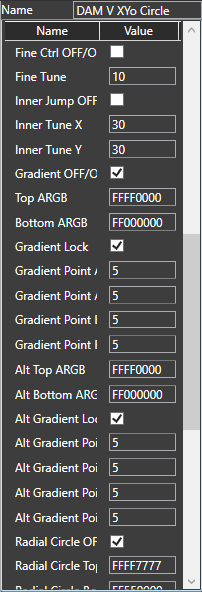
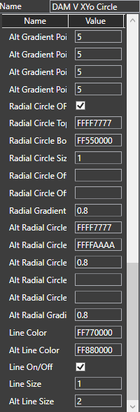
DAM V XYo Circle,
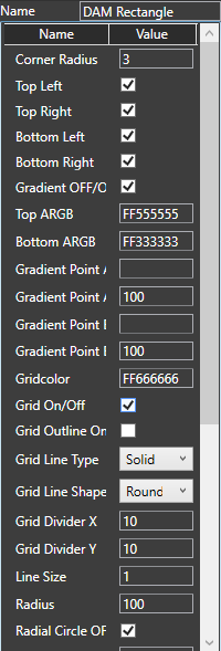
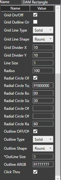
DAM Rectangle.
Elena’s ED GUI Modules;
ED GUI Fixed In,
ED GUI Fixed Float,
ED GUI Timer.
Once again I’m going to stress that you should never convert from a GUI signal to DSP, perform a math or timing function, then convert this back to a GUI signal. It’s very wasteful on CPU resources, and can cause many problems.
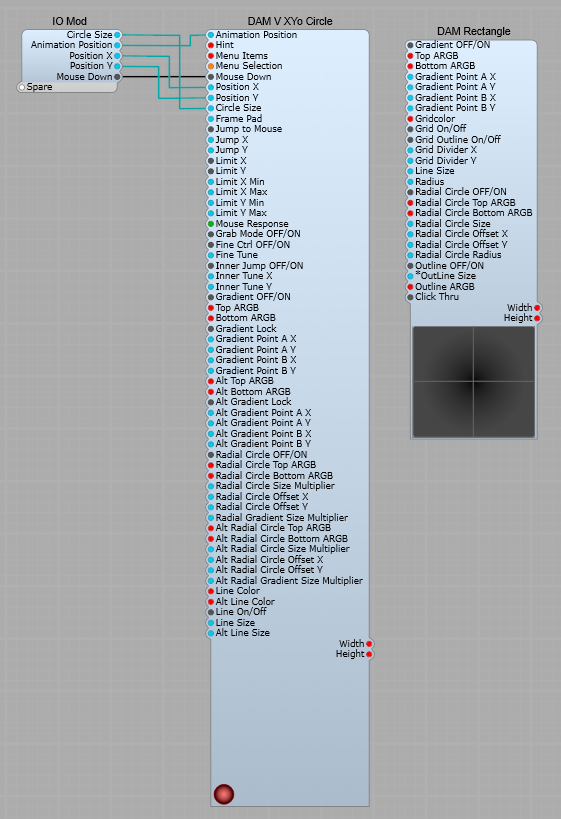
GUI Container for the Joystick.
The Joystick control iteslf uses the DAM V XYo Circle module. This resturns the position of the circle, which can be extensively customized. Here I have pre-set it with a red theme. In the interests of simplicity I’m just connecting the following plugs to the IO Module;
1) Animation Position- The output value of this plug is 0 till the circle receives a click (Mouse Down), it then changes to 10.
2) Position X- The X co-ordinate (horizontal) of the circle (Normalized value of 0-1)
3) Position Y- The Y co-ordinate (vertical) of the circle (Normalized value of 0-1)
4) Circle Size- The size in px of the circle.
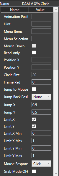
The settings in the properties panel are shown below. Make sure the Jump Back Position List is set as “None”, the Mouse Response is set to “Click”, and The Gradient Lock check boxes are ticked. These are the colour settings I used, but as always that’s your personal choice.
Mouse response- This selects various modes, the main ones are;
None- Nothing happens when you click on the circle, and it’s locked in position.
Click- Click on the circle and the Animation Position changes to 10, the circle assumes its “Alt” colour scheme, and can be moved.
Step- Click on the circle and the Animation Position changes to 10, the circle assumes its “Alt” colour scheme and the circle can be moved. The Animation Position value and “Alt” colours are held until a second mouse click is received.
Settings for the DAMV XYo Circle and DAM Rectangle modules.
I have shown these settings as screenshots.
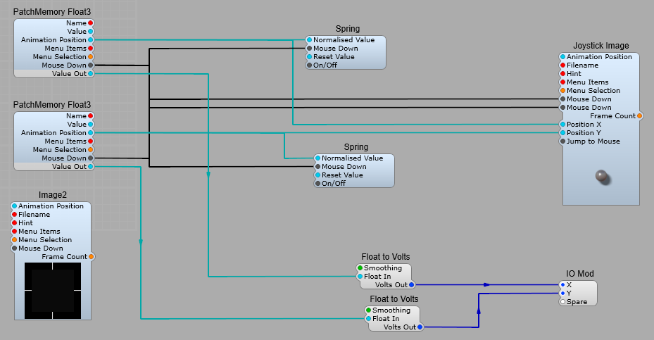
The control section.
The x and y output values are passed as usual to PatchMemory Float3 modules. These then send the Float values to the output IO module as GUI Float, DSP Float and Volts. The Volts as usual is converted by the stock Float to Volts module.
Returning the Joystick to the centre position.
This is done with a pair of Spring 3 modules to send a value of 0.5 to the Position X and Position Y plugs. The ED GUI Timer is used to send a short (10 mS) pulse to the Spring 3 modules when the Centre On/Off plug is set to true. (I found that the Joystick wasn’t reliably setting to the centre when switched on otherwise).
Setting the Joystick’s output ranges.
As usual the ranges of the output values can be specified via the Patch Memories. To make this easier I recommend changing the Patch Memory names in the Properties panel to something like x-axis range, and y-axis range.
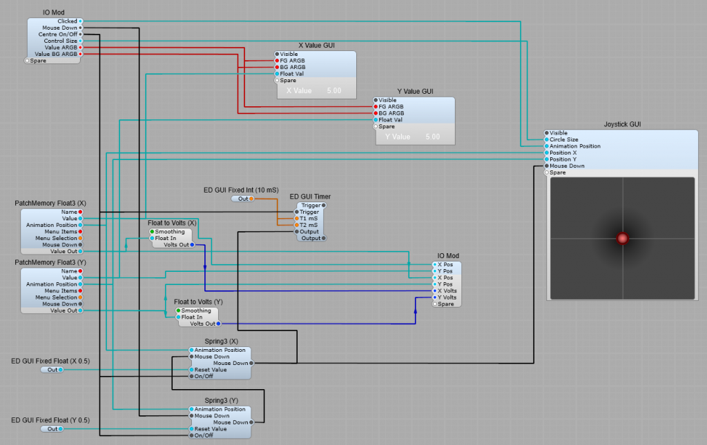
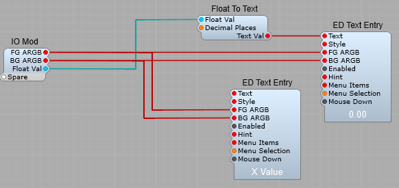
X and Y Value (GUI) containers.
These are just standard Float to Text conversion, both connected to the Value output of the PatchMemories to show the actual value being output by the joystick, rather than the Animation Position.
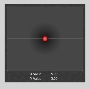
The control panel view.