Stuck with a SynthEdit project?

Category: Echo

Tempo synced Echo.

How to sync an echo plug in with your DAW.

It’s often very nice to be able to synchronize an echo delay time to the song tempos in your DAW, you can get some nice rhythmic effects like this.

Getting the BPM from your DAW.

This prefab will allow you to enter the echo delay time in beats rather than in milliseconds. Sorry but we need some basic math to do this:
The BPM Clock2 module provides the DAW tempo in volts. It’s a direct relationship 60 BPM = 60 V, 120 BPM = 120 V and so on.
As we already know one minute = sixty seconds,
so we need to divide 60 by the tempo (voltage) in BPM to get the voltage required for one beat (This is provided our delay module is set up correctly) Setting up the delay comes later in this page.
Now, for instance if we have 120 BPM: 60/120 = 0.5, therefore a beat is 500
milliseconds long. Now what if you want to synchronize your delay to
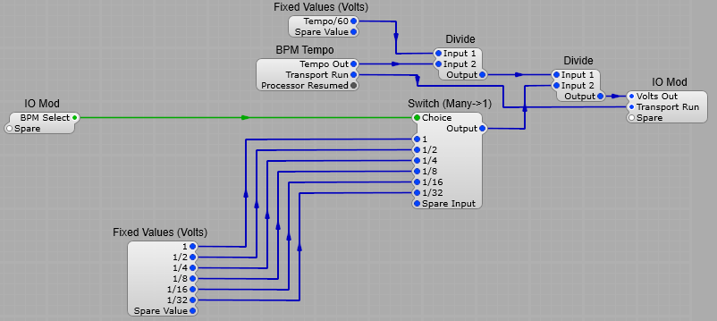
halves or quarters rather than whole beats? All that’s needed is to set up another divider which divides the the beat’s length by 2, 4, and so on to arrive at 250, 125, or another step converted to milliseconds for your delay. The structure for this part of the Echo is shown below. Our fixed voltages are 1, 2, 4, 8 and so on.
Note: When in SynthEdit this will only run at the default tempo of 120BPM.
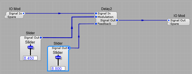
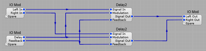
Delay modules.

The delay section is quite simple, all that’s needed is our two delay modules in a container. Make sure you have the Delay Time set at 1 second in the properties panel.

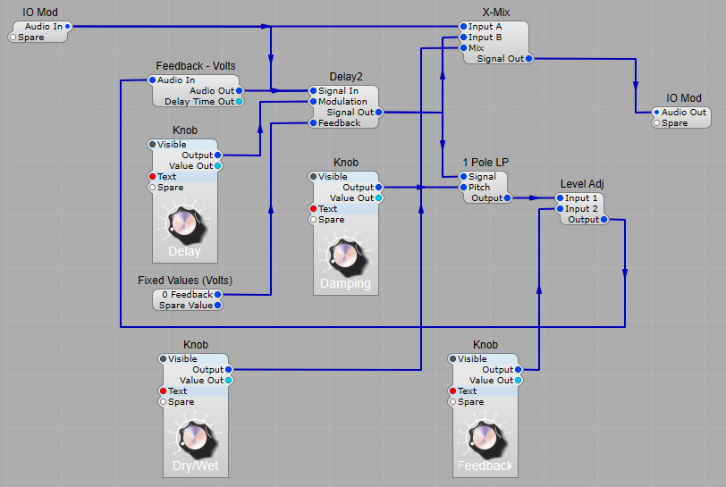
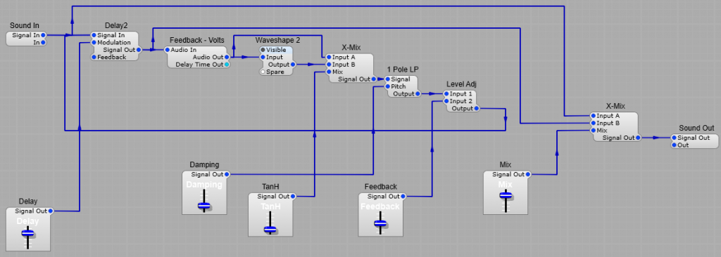
The complete BPM Synchronized echo is shown below.

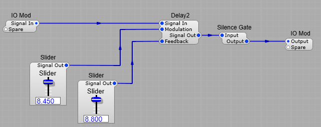
This is good so far, but if you want to have an external feedback loop so you can introduce filtering etc. in to the loop, then because of the (unavoidable) latency in the Feedback Volts module the timings will go astray a bit causing some unwanted comb filtering effects.

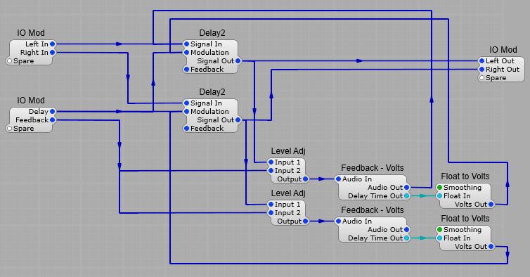
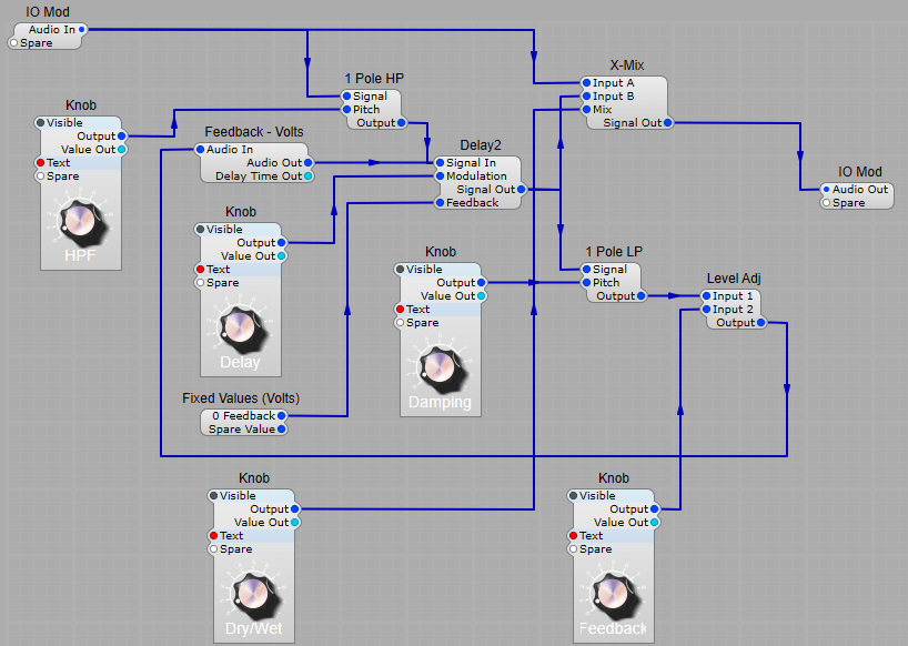
Time correction in external feedback loops.

Fortunately there’s a handy output plug on the Feedback-Volts module the Delay Time Out, we just need to convert this from Float to Volts and apply the correction voltage to the Delay 2 modules, this will then alter the timing of the delay slightly to compensate for the Feedback Volts latency so that the feedback and the original signal can remain in sync.

Improving CPU usage with Delay 2

What is the CPU usage issue with Delay2?

Consider the structure below, with the settings we have on the controls, there could potentially be a very long “tail” on the echo with such a feedback level. Ok so it reaches a low level, but it could take a very long time to reach what SynthEdit considers “silence”. Why does this matter?
Well any modules further downstream are not getting shut down as they should be, and could still be active long after the human ear would fail to detect sound from the echo. This is a waste of CPU, as these modules are relying on SE telling them that they are not receiving audio, meaning they may not go into “sleep” mode for a long time. There is no risk of generating “Denormal” numbers as SE removes these internally.

Here is a quote from a regular contributor on the SE group Andrew Ainsley:
“I sleep my modules when it is approximately under -110dBFS(noise floor of the best high-end AD converters, and humanly detectable dynamic range is approximately 120dB), and I’m assuming Delay2 sleeps at somewhere just before denormal mode, which is very very low, I tested up until -250dB and Delay2 is still active for quite some time afterwards…In practice say, with a max delay of 1 sec and 50% feedback, Delay2 will take in the order of minutes to go to sleep, which in practice is longer than a typical song, which seems rather pessimistic to me – i.e. in practice it will never sleep even though it can sleep, and thus it also keeps downstream modules awake while processing an inaudible signal. Switching it off sooner (in level) might cause audible clicks, but even if you assume the end-user will boost the level by an unrealistic value of say +120dB(!), you should still be safely able to switch off at about -230dBFS. “

If we look at the chart below you can see what is meant by the tail, the red section is where the reverb/echo is tailing off (The purple section). At high feedback levels this tail can potentially become very long if there is no cut off point set other than 0, even though we can’t hear the sound. We want to keep the green and blue sections, but it would be very handy to be able to remove the inaudible section of the tail.

Reverb/Echo tail illustration

How can we stop this waste of CPU?

Fortunately Jeff has introduced a new module in SynthEdit to prevent this issue-the Silence Gate. This module does not wait for complete silence (0), but shuts off the audio at a level where we can’t actually perceive the sound. (Jeff has not quoted a level for this, just that it is completely inaudible.

Adding extras to echo.

Adding damping to the echo.

The first addition to echo which goes a long way to creating a more natural sounding effect is damping. What exactly is damping?
When we hear echoes in a large room, hall or any large space, especially if there is an audience or any form of furnishing, is that the higher frequency sounds tend to get absorbed, and reduced in level. We can emulate this easily with a 1 pole LPF, the frequency of this can be varied creating a variable amount of damping. We just need to set up a feedback loop with a Feedback – Volts module, our 1 pole LPF, and a Level Adjust module.

Adding a low pass filter to introduce damping to the feedback

It’s not “All about the Bass”.

Sometimes (well quite often) we don’t want too much bass entering an echo as it can make the sound “muddy” and even overpower the higher frequencies. Adding a simple 1 pole HPF on the input of the Delay 2 module can help greatly with this by cutting out those troublesome lower frequencies

Adding high pass filtering to the delay

Getting a “Tape Echo” sound.

What is Tape Saturation?
It’s a subtle effect that occurs as the magnetic particles in a recording tape (remember reel to reel recorders?) are asked to record too higher signal level it introduces a slight harmonic distortion, and a soft clipping effect. What some would refer to as a “warm analogue sound”. Used sparingly it can add to an effect such as echo to reproduce some of the old tape delay effects units.
Examples of these were Roland Space Echo, Korg Stage Echo, and the famous Watkins WEM “Copycat”.
The distortion in these machines was a result of several factors:
The design of the amplifiers
The amount of tape “bias”
The type of recording and playback heads
The type of tape
The amount of feedback used.

Getting the “saturated tape” effect.
This can be done by adding a subtle distortion using the TanH formula. I have used a Waveshaper 2, for a tape effect it only needs to be a subtle amount, and nothing too harsh, so TanH is the ideal formula for imitating a soft tape saturation effect. An example of a TanH curve is shown below (full formula 5*tanh(x) along with the effect on a sine wave (yellow is direct from the oscillator).

5*tanh(x)
5*tanh(x)

We can soften the effect more by a simple modification of the formula to 5*tanh(x/2)

5*tanh(x/2) shaping
5*tanh(x/2)

Or the distortion can be increased by changing to 5*tanh(x*2)

5*tanh(x*2) shaping
5*tanh(x*2)

The depth and harshness of distortion is directly related to the multiplier or divisor vale for x. The greater the divisor the softer the effect, the greater the multiplier the harsher the effect. My suggestion would be to use a formula along the lines of 5*tanh(x/3), or for an even more subtle effect 5*(tanh/4)

5*tanh(x/3) shaping
5*tanh(x/3)

The Finished “Tape Echo”

Here is the final version. I tested a few modules for the saturation effect, and found the best sounding one seemed to be the stock waveshaper 2 using the formula tanh*(x/4).
The X Mix module on the waveshaper output is to give control over how much of the distorted and undistorted sound is used in the feedback loop.
Note: Don’t forget to set the feedback level on the Delay 2 module to 0, as we are using an external feedback loop.
Creating a stereo Echo is as simple as duplicating the effect and using the same controls for both channels. I containerized the Waveshaper 2,and left it as a non-visible module so that it’s not shown on the panel layout, and therefore not available to the used to change the saturation formula in the waveshaper.

Creating a Multi-Tap Delay in SynthEdit.

At its most basic level, a multi-tap delay, is a delay effect with multiple outputs, or “taps”. Each of these taps can be set to a different delay time, and a different level, meaning that the delayed sound is played back multiple times at different intervals and levels. This differs from a traditional delay effect, which typically only has a single output with a set delay time, and a gradually decaying repeat. Traditionally in the analogue world this would be done either with a tape delay using multiple playback heads, or using multiple BBD delay chips.

Multi-Tap delays in VST effects.

In a digital setting, multi-tap delay is achieved by creating multiple delay lines within a delay unit or plugin. Each of these delay lines can be adjusted together or independently, allowing you to control the delay time, feedback, panning, and even the tonal quality of each tap.

One of the main characteristics of multi-tap delay is its ability to create complex rhythmic patterns. By setting different delay times, and audio levels for each tap, you can craft intricate rhythmic structures that can add movement and depth to a mix. This can be particularly effective in genres that rely heavily on rhythm, such as electronic and dance music.

Additionally, multi-tap delay can be used to create unique sonic textures. By manipulating the feedback, panning, and tone of each tap, you can create a wide range of effects, from swirling, stereo-enhanced delays to dense, reverb-like textures.

A simple delay is an effect that introduces a single repetition of the signal with a delay in time and slow decay in amplitude, whereas a Multitap Delay is a sequence of simple delays. The output of each simple delay feeds into the next simple delay and back into the input. This creates an echo, but not one that simply decays constantly over time. The multitap delay echo may decay, but then peak at some points, or may contain echoes of the echo.
A multitap delay can be simulated with a ready made tapped delay line, but we don’t have one in the standard SynthEdit Modules (Although there is a third party module from TD Modules).
Adding a large number of taps, especially if feedback is added, will create a very complex effect.

Creating our Multi-Tap Delay with SynthEdit

A basic Multi-Tap effect (without controls, feedback and mixing for simplicity) is shown below:

The Multi-Tap Delay:
This is just a chain of Delay 2 modules connected in series, with each Delay tapped to send to an output Tap 1, Tap 2 etc.

The Mixer:

The Feedback control:
Nothing too special here, except that the 1 Pole LP has its Frequency scale set to 1kHz per Volt in the module properties.

The Delay Effect in Full:

In the structure the only point of note is that the cutoff control slider for the Low Pass Filter in the Feedback container has it’s minimum set to 0.5 V corresponding to 500Hz, and it’s maximum set to 5 V corresponding to 5kHz (this isn’t critical however, and can be changed to suit tastes). The filter in the feedback module provides the sort of frequency response degradation you would expect to find in most analogue or BBD delay effects pedals, where each time the audio “goes around” in the loop high frequencies are progressively lost.
The Left and Right channels are both fed through the same delay line, and split again at the output, however, if you wanted a more complex stereo effect then you could duplicate the structure and connect this to the second audio channel to achieve a delay with the Left and Right channels being controlled separately from each other.

If you want to the effect can be made very complex, by using panning to adjust the position of each Tap in the stereo field, filtering the output of each tap individually…it’s limited by your imagination.

Ping-Pong (Cross) Echo.

A Ping-Pong Echo is much like a normal echo, except that its a stereo effect and the left signal feeds back to the right channel, and the right channel feeds back to the left channel, bouncing the signal back and forth across the stereo field.
Hence the term ping-pong delay. Shown below is a schematic diagram of a cross delay.

Basic block diagram of a ping-pong delay

Creating our Ping-Pong echo in SynthEdit.

To create a Ping-Pong Echo in SynthEdit we must use an external feedback path rather than the Delay2 module’s internal feedback circuit and as you know if you try to create this structure with a normal feedback path, you will get the error message: This patch contains a FEEDBACK path, Please remove.
We get round this problem using a pair of Feedback – Volts modules to create feedback paths that are acceptable to SynthEdit.
See the layout below:

Simple ping-pong delay in synthedit

For the sake of simplicity I have kept to one set of controls for both left and right channels, but there’s nothing stopping you from having separate controls for left and right channels.
Of course you can build on this to add HF Damping into the feedback loop, displays to show the delay time etc.