Switching when a Variable voltage matches a Fixed voltage within a set range.
Have you ever needed to trigger an event when a Control Voltage is within a narrow range of values? There is a stock comparator, but on its own this will only give you a true or false if the voltage is above or below a set value. This prefab will tell you within a very narrow range when the Variable input is equal to your Reference input and output a “True” value. (I have tested this to a +/- 1mV range either side of the Reference). This prefab uses no 3rd party modules.
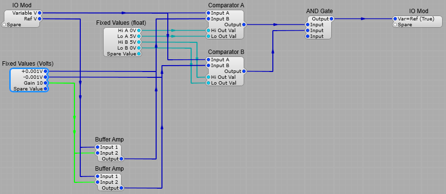
How the Voltage Detector works.
Comparator A sends a True value when the Variable is within the range -0 to -0.001 V of the Reference voltage. Comparator B sends a true value when the Variable is within the range +0 to +0.001V of the Reference voltage. These two voltages can be set to give the detecter a wider or narrower range. With these values Comparator A and Comparator B will both output a “True” value when the Variable is within + or – 1mV of the Reference. The AND Gate will only output a value of “True” when both inputs are “True”. The Buffer Amps are just Level Adj modules with a 1:1 gain to prevent the two comparator References interacting.
This module produces a random train of 100 mS long pulses, and a randomly varying control voltage, the minimum and maximum values of which van be varied.
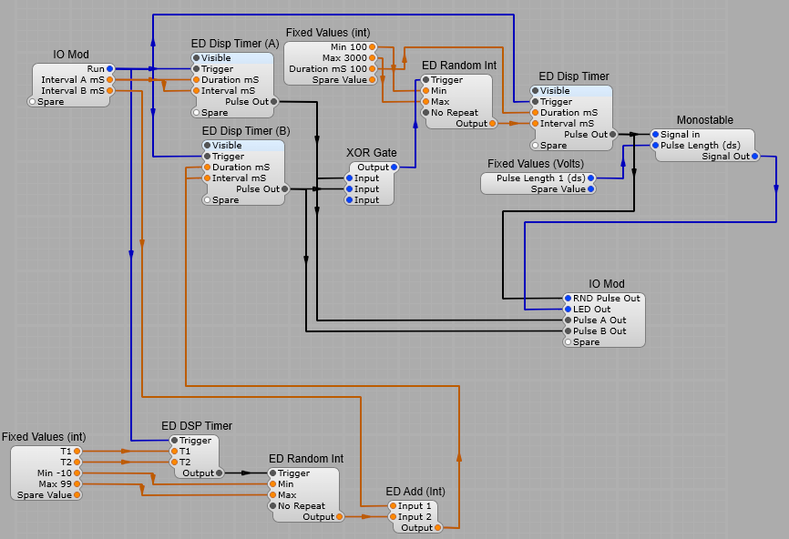
The Random Pulse Generator.
The principle of this module is that it produces two unsynchronized pulse trains running at different speeds. Pulse train B continually (1 second intervals) has a random value added to the Interval B mS setting by a an ED Random Int generator when the Module is triggered by a the ED DSP timer. Pulse train A and pulse train B are fed into an X-OR gate. This produces a pulse whenever A or B is high, but not when both are high. The result of this is a pseudo random chain of pulses sent to the ED Random Int generator which outputs a new integer between 100 and 1000 each time it receives a Trigger pulse. The random integer is then fed to the Final ED DSP timer which is set to produce 100mS pulses with an interval set by the Random Integer. This is fed to the RND Pulse out and a Monostable with the pulse Length set to 1 dS, this is used to flash an LED each time a pulse is output. The structure of the Random Pulse Generator is shown below.
Note: This project relies heavily on Elena Novaretti’s module pack. The modules used in the project are; ED Random Int, ED DSP Timer, ED Add Int, ED Level Bar 2, ED Random Volts, ED Glider 2.
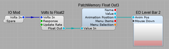
The Level Indicator.
This is just used as a visual indicator of the CV level being generated.
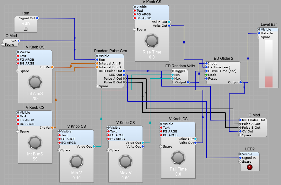
The Complete CV and Timing Randomizer.
The RND Pulse out is fed into the ED Random Volts module. Each time this is triggered a new voltage is randomly generated. The Minimum and Maximum range of the output voltage is set bu the Min and Max knobs. The output voltage is fed to the ED Glider module. This module allows the rise and fall times to be set. The Glider mode should be set to constant time.
The first complex CV generator uses a pair of Time Domain modules X-Mix modules to gradually morph between four Time Domain LFO modules. All the LFOs can be set to run at different rates, and have different wave-shapes making a very versatile CV generator. The morphing is likewise controlled by two more Time Domain LFOs. The Multiplier module has a value of 2 on it’s Input 2 plug to give the correct scale for a GUI Level Bar indicator. The Fixed Values (Volts) Module has an output of 5V, as the output from the TD X-Mix modules has a maximum of +/- 5 V, so we want to convert the minimum -5V to convert to 0V for the meter. The offset control is fed to input 2 of the second Level Adj module so as not to affect the readout of the level indicator.
Sometimes you need a special module to control Filters or Oscillators.
TD_EnvFollow_A Envelope Follower Type A This is a simple envelope follower based on “traditional” analogue effects pedal design. This module does not do any filtering, you will need to connect a filters cut off control to the output plug! The input is internally rectified, so you also save a module in the process. The attack and release time pins only update at SE’s internal block-rate. Note: This is a typical type of envelope follower found in guitar pedals and some High-End compressors. The release time should always be much larger than the attack time, otherwise the envelope following isn’t very accurate. If the release time is too short the effect it is being used in will produce distorted audio due to the input waveform modulating the output (which is how the original effects pedal would normally behave).
Typical Envelope follower application:
TD_EnvFollow_B Envelope Follower Type B Notes: A simplified envelope follower based on traditional analogue design techniques. The input is internally rectified – so you also save a module in the process. Attack and Release time pins only update at SE’s internal block-rate. For the technically inclined: This topology is unique because internally it releases before it attacks. The actual release time is T-attack + T-release, but usually attack is much shorter than release so this isn’t very audible, it does however reduce intermodulation distortion more than the regular switched coefficient method. The native SE envelope is a switched coefficient type, as is all other. This method does change the release trajectory somewhat. This does not use TPT/ZDF but the Step Invariant method instead to realize the topology.
TD_Quantizer Mono voltage quantizer. Notes: Suitable for control voltage or audio-rate signals. The module quantizes the input voltage according to step size, that is it constrains the input voltage change to pre-set steps of the value specified. Minimum step size is 0.0000001V. This module uses less CPU than the stock SynthEdit version.
TD_Quantizer_ST Stereo voltage quantizer. Notes: Suitable for control voltage or audio-rate signals. The module quantizes the input voltage according to step size, that is it constrains the input voltage change to pre-set steps of the value specified. Minimum step size is 0.0000001V. This module uses less CPU than the stock SynthEdit version.
TD_Contour Voltage contour modifier, select for a list of pre-set formulae. Notes: The easiest way to see what the modes do, is to connect a sawtooth wave of +/- 5 volts to the input and then check it on a Scope. Predominantly made to alter the response of a VCA (use with Level Adjust), but can be used for other things too. Modes:- Thru, Mirror, Clip0/10, Expo1, InvExpo1, Expo2, InvExpo2, Expo3, InvExp3, Square, InvSquare, Log1, InvLog1, Log2, InvLog2, Log3, InvLog3, Sqrt, InvSqrt, Pow.25, InvPow.25, Scrv, InvScrv, SqrScrv, SqrInScrv, Gate40, Gate34.
TD Curver. Control voltage curve modifier. Input voltage: the range is within the 0 to10 Volt Range. This input is internally clipped to these levels.. Curve Amount: the range here is also 0 to 10 volts. 5 Volts = Unchanged input signal appears at the output. Again the easiest way to see the effect is to experiment using a sawtooth input and a ‘scope on the output. Some of the results I have obtained are shown below
TD_PeakHold Peak Hold Filter Notes: This module is generally used as a Peak hold for GUIs, and is not recommended for audio use. (You need to use a DSP-GUI bridge or Patch Mem)
TD_PeakHold_ST Stereo peak hold filter Notes: Generally used as a Peak hold for GUIs, and is not recommended for audio use. (You need to use a DSP-GUI bridge or Patch Mem)
Quantization is used to constrain a control voltage to discrete steps. The module takes the amplitude of the input voltage and breaks it down into the steps specified by the voltage on the Step Size control plug. Quantization is used on control voltages for pitch an filter cut-off voltages. (No reason why you can’t apply it to audio, but the correct module for audio is a Bitcrusher which gives you better control). Quantization is often used for generative and ambient music. The Synthedit Quantizer will work on Audio signals, and progressively reduce a sine wave signal form the original sine wave, through a stepped sine wave to a pulse waveform, which is quite different in effect from a bit-crusher (bit reducer). Note: all a quantizer will do when applied to audio is to introduce distortion, it does not introduce any frequency changing or shifting effects.
Plugs. Left Hand Side:
Signal In:- (Voltage) Control Voltage Input signal Step Size:- (Voltage) Quantisation step size in Volts
Right Hand Side:
Signal Out:- (Voltage) Quantized Control Voltage output.
The screenshot below shows the effect of quantizing a +/- 5 Volts sine wave. Note: In some cases the peak-to-peak voltage of the output will actually be greater than the =/- 5 Volts input to accommodate the correct voltages between each step.