The simple answer is that all the standard SynthEdit oscillators use what is called “Hard Sync”, which is an “all or nothing method. Using this method of “soft sync” allows control over how much sync is applied to the VCO. What we do is take a portion of the Master (Sync) Oscillators wave form as it crosses zero, and use this to Phase Modulate the Slave (Audio) Oscillator.
Third party modules:
There are two third party modules used for prefab the ED Zero Crossing Detector, and the ED Flip Flop (Audio). The Oscillator HD is one of the community SE modules available from the SE website.
The Soft Sync Master/Slave oscillator.
This consists of our two oscillators (master and slave) the output of the master is fed to the ED Zero Crossing Detector, which generates a very short (1 sample long) pulse everytime the output of oscillator 1 crosses 0 volts. We can set the detector to trigger on either the rising voltage, the falling voltage or both rising and falling. This is fed to the ED Flip Flop (Audio) which is used as a bistable so the first pulse triggers a “High” output, then the second resets the output to a “Low” output. This allows us to gate a one cycle long burst of the Master oscillator signal of variable ampliture to feed to the Slave Oscillators Phase Modulation plug. What we are effectively doing is using the output of the Master Oscillator to gently (or not so gently) change the phase of the Slave oscillator, thereby changing its output shape to a greater or lesser degree. Note: If you are intending to use large levels of Sync, or waveforms (such as ramp) with fast rise/fall times you will introduce aliasing, so it’s good policy to include oversampling in the Master/Slave Sync Oscillator’s container to limit this. The 1 Pole HPF is included to cut out any “LF rumbles”, or possibly DC from any aliasing produced by very fast phase changes.
Settings and values.
Settings for the ED Flip Flop are: V Threshold: 0.01 V. This is the input level at which the flip flop triggers and switches state. V Out: 10V. Both slave and Master Oscillator HD: Reset Mode: DCO (Sync). 1 Pole HP: Freq Scale: (Properties) 1kHz per Volt. Pitch: 0.014 (14Hz) Sync Gain: Level Adj Input 2: You can use the default of 0 to + 10V, but you can also go from -10 V to + 10 V which allows the sync to use phase reversal in the modulation.
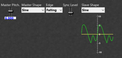
Master 1 octave above Slave.
As you can see below changing the edge detection also affects the resulting output signal from the slave oscillator.
Rising edge zero crossing detection.
Falling edge zero crossing detection.
Using both rising and falling edge zero detection.
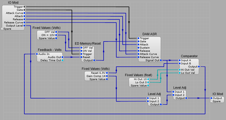
The stock ADSR module can be used as an Attack/Decay module, but it can under some conditions produce loud “pops and clicks” especially when used with a fast attack time (the so called exploding envelope bug). So far I have found no problems with this prefab with very short envelope attack times.
Third party modules required.
There are two third party modules required for this prefab, namely Elena’s ED Memory/Reset module, and Davidson’s DAM ASR module.
The Attack/Decay generator.
I used the DAM ASR module, but the module itself has a sustain built in after the attack segment is complete, and I wanted to go into the Decay (Release) segment immediately the peak of the Attack segment was reached. To do this I used a comparator to detect when the ASR module reaches 6.9 V (this appears to be the maximum), this is then fed back to the ED Memory/Reset module which resets the Gate signal to 0V. I know this is feedback loop with it’s inherent latency, but the few samples worth of delay really doesn’t cause any noticeable issues with the operation. The Curve plugs control the shape of the Attack and Decay segments individually, from a log curve, through linear to an exponential curve. Attack and Decay timings use the same formula for the stock ADSR module’s Volts to Seconds timing conversion. The first Level Adjust module is used to bring the AD envelope to the ususal 0 to 10 V range with the standard 0-10V slider control range. Note: As with the standard ADSR using a slider range of -10V to +10V gives both normal and inverted envelopes.
Unless you are a Linux/Ubuntu user you may not be familliar with the Zita Reverb. It’s a reverb effect that combines elements of Schroeder and FDN reverberators in a complex matrix of delays, all-pass comb filters and damping filters.
The Zita reverb has two separate delay times for low, and mid/high frequencies. There is a crossover frequency control to set the frequency where low becomes mid frequency range. The mix between the two reverb bands can be varied, as can the EQ for the frequency bands. The mixer also has a pre-delay time adjustment. Pre-delay is the amount of time before the onset of the reverberation effect. Longer pre-delay settings will add more depth to the reverb when the dry signal is up front in the mix.
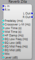
Plugs. Left Hand Side:
L in:- Left hand side audio input. R in:- Right hand side audio input. Predelay (ms):- Sets the Pre-Delay time in milliseconds. Pre-delay is the amount of time before the onset of the reverberation. Crossover L-M (Hz):- Sets the Low to Mid crossover frequency. Low Time (s):- Sets the low frequency reverb decay time. Time (in seconds) to decay by 60db in the low-frequency band. Mid Time (s):- Sets the mid frequency reverb decay time. Time (in seconds) to decay by 60db in the mid-frequency band. HF Damp (Hz):- Sets the HF Damping frequency. EQ Low Freq (Hz):- Sets the low frequency reverb boost/cut EQ frequency EQ Low (dB):- Sets the low frequency reverb boost/cut EQ amount EQ Mid Freq (Hz):- Sets the mid frequency reverb boost/cut EQ frequency EQ Mid dB:- Sets the mid frequency reverb boost/cut EQ amount Mix:- Sets the mix between direct signal and reverb. Level dB:- Sets the output level in dB.
Right Hand Side:
L Out:- Left hand side audio output. R Out:- Right hand side audio output.
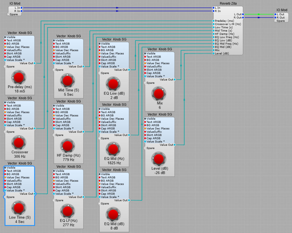
Structure of a typical Reverb effect prefab using the Zita Reverb module.
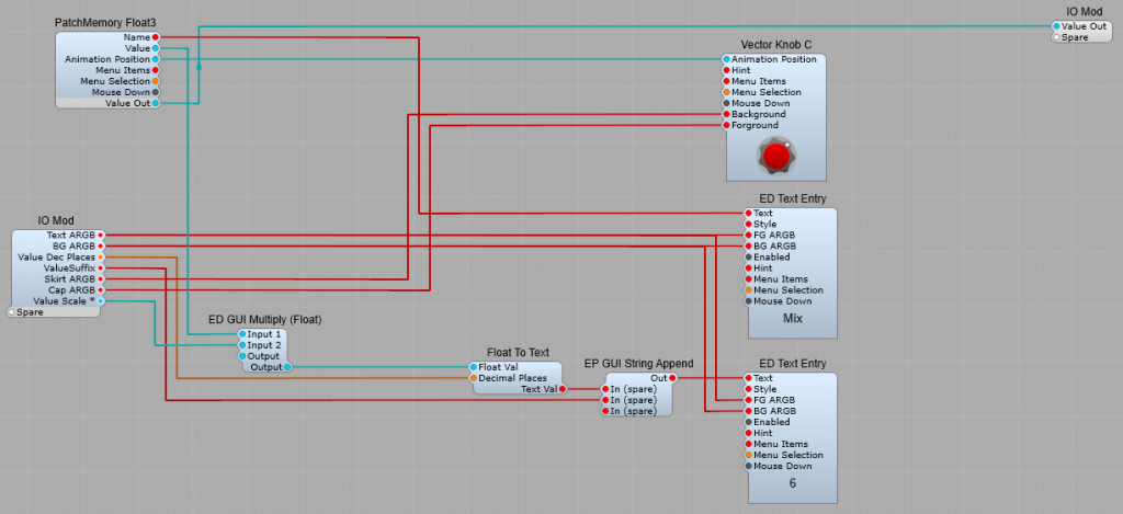
Structure of the Float output knobs.
Nothing very special-just that the Float to Volts converter is removed, and the DSP Value out is taken directly to the IO Module plug.
Setting up the control ranges.
There are no conversions needed for the controls and the value readout as the Float values are either Float Value=dB, or Float Value=Hz. Keeps things nice and simple. Pre-delay: A good range is 0 to 200 (mS). Crossover: 10 to 2000 (Hz). Low Time: 0.5 to 10 Sec (Don’t leave the “Low” as 0, the reverb will crash until the audio/plug-in resets). Mid Time: 0.5 to 10 Sec (Don’t leave the “Low” as 0, the reverb will crash until the audio/plug-in resets). HF Damp: 10 Hz to 10 kHz. I have seen the upper frequency suggested as 20 kHz, but that seems unnecessarily high to me. EQ Low Hz: 10 Hz to 1000 Hz. EQ Low dB: -20 dB to +20 dB. EQ Mid Hz: 1kHz to 10 kHz. EQ Mid dB: -20 dB to +20 dB. Mix: 0 to 100. Level (dB): A good range would be -40 dB to +10 dB.
Typical Settings.
Predelay: amount by which the “wet” signal is delayed relative to start of the “dry” signal. The range is usually between 0 to 200 ms, a good default is 60 ms. Crossover Freq: The crossover frequency separating the low and middle frequencies, The range is 10 Hz to 1000 Hz, a good default setting is 200 Hz. Low Release: The time for the reverb to decay by 60 dB in the low-frequency band. The range is 0.1 to10 seconds, a good default setting is 3 seconds. Mid Release: The time for the reverb to decay by 60 dB in the mid-frequency band. The range is 0.1 to10 seconds, a good default setting is 2 seconds. Damping Freq: The frequency at which high- and mid-band decay release times are equal, The range is 10 Hz – 10 kHz, a good default frequency is 6 kHz. EQ Low Freq (Hz): The center frequency of the Low EQ, Frequency range is 10-1000 Hz, a good default is 315 Hz. EQ Low (dB): The peak level of EQ section 1, The range is from -20 to +20 dB, default setting 0 dB. EQ Mid Freq (Hz): The center frequency of the Mid EQ, Frequency range is from 1 kHz to 10000 Hz, a good default setting is 1500 Hz. EQ Mid (dB): The peak level of Mid rangeEQ, Range between -20 to +20 dB, default 0 dB. Dry/Wet Mix: percentage, 0 (all dry) to 100% (all wet), a good starting point for an instrument is 50% (see below).
Tips for using Zita Reverb.
Use the Low Time and Mid Time settings. Adjust Low Release to control the tail length for low frequencies, and Mid Release for high frequencies. The ability to adjust these separately is the main distinctive characteristic of the Zita reverb vs. other reverbs. Damping. Increase Damping Freq for a bright sound, reduce for a dark sound (this also reduces tail length). Hint: excessively bright reverb sounds un-natural as high frequencies decay more rapidly than low frequencies. EQ Settings. Note: Be careful with the Low EQ settings as these can make your final sound a bit “boomy” at the bottom end- I have seen this as a criticism of Zita reverb being “boomy”, it’s not if it’s used with careful attention to the LF controls. Experiment with the EQ controls to balance tail length and tonal balance that suits your music. Don’t be afraid to experiment. Pre-Delay. If the idea of pre-delay seems confusing at first-you’re not alone, it took me a while to grasp it too! The Predelay setting allows you to delay the start of the wet signal (reverberated) relative to the start of the “dry” signal, to allow the dry signal to stand out in the mix with a clean “punch”. This keeps the mix from sounding “muddy”. Try using longer Pre-Delay time settings for creative effects. Reverb Mix levels. When using as an in-line effect on an instrument, you would normally keep the Wet Level below 0.5. Low values can be subtle but quite effective. When using as a Send effect set the mix at 100% so you get the full range of control over the mix on the return level stage.