Stuck with a SynthEdit project?

Month: August 2025

DAM V List Block Grid

Using the List Block Grid.

This is a very handy module to replace the drop down List Entry module with.
Instead of the Windows style list we can have rows and columns of buttons.
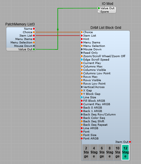
Connecting up the module is simple, see below:

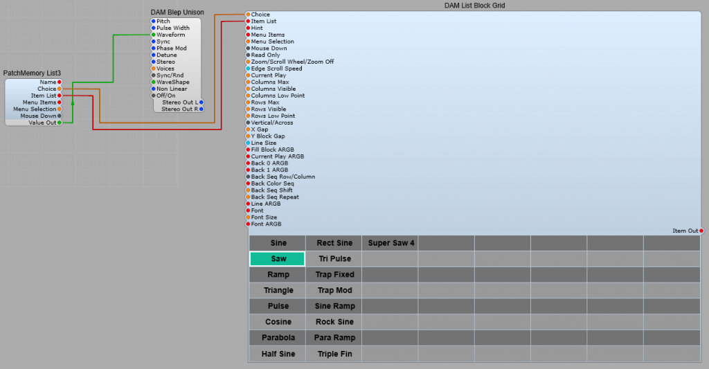
As you can see it’s the usual “hook up” connect to a Patch Memory List3 using the Choice and Item List plugs, the the Value out from the Patch Memory to the DSP module that requires a list selection. As usual there is a default list created from the DSP module via the Patch Memory. So far so good, but all those empty “buttons” aren’t good, and the colours may not match.
The beauty of this module is it’s very customizable, however there are some parts that I found were not immediately obvious without some experimentation. I will do my best to explain these clearly.
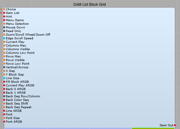
First, the Plugs.

Choice: (Integer) Select one of the items in the item list in the drop down list using the items Integer number. Note: The first item in a list is always 0 (Not 1)
Item List: List of items to be included in the list.
Hint: Pop-up hint displayed when the mouse pointer is over the control
Menu Items: List of items in the right click menu.
Menu Selection: Select one of the items in the Menu Item list in the drop down list using the items Integer number. Note: The first item in a list is always 0 (Not 1).
Important Note: Menu Items and Menu list are not the list that is generated by the DSP Module, they are the right click menu!
Mouse Down: Outputs a pulse when the block receives a mouse click,
Read Only: When set to “True” the List Block Grid only receives the selection, it cannot send an output.
Zoom/Scroll Wheel/Zoom Off: Allows use of the mouse wheel to Zoom or Scroll the button grid. Note: When used inside SynthEdit you need to hold down the CTRL + ALT
Edge Scroll Speed: Controls the Zoom /Scroll rate.
Current Play: This button is always the colour set in Current Play ARGB, but this does not affect the List output selection. -1 means no button is made “Current Play”. Note: Button numbers start from 0.
Columns Max: Maximum number of columns available.
Columns Visible: Maximum number of columns visible.
Columns Low Point:
Rows Max: Maximum number of rows available.
Rows Visible: Maximum number of columns visible.
Rows Low Point: If the number of Rows Visible is smaller than the Rows Max value then Rows Low Point sets the point in the list where the list starts displaying.
This is not intuitive so I explain this in more detail later.
Vertical/Across: Sets whether the display of List Items run in a Horizontal or vertical sequence starting from the top left hand corner.
X Gap: Horizontal spacings between buttons.
Y Block Gap: Vertical spacing between buttons.
Line Size: Size in Pixels of the Current PLAY ARGB, and the Line ARGB border lines surrounding the selected button.
Fill Block ARGB: The colour of the selected button. This is your button that changes colour when you have clicked on a choice
Current Play ARGB: The Border colour of a button changes to this colour when the button is clicked, as soon as the left mouse button is released it becomes the selected Line ARGB colour.
Back 0 ARGB: Sets the Row/Column Background 0 colour.
Back1 ARGB: Sets the Row Column Background 1 colour.
Back Seq Row/Column: Sets whether the Back Colours appear as vertical or horizontal stripes.
Note: The sequencing of Row/Column colours is not completely intuitive.
I’ll explain this after explaining all the plug functions.
Back Color Seq: The sequence in which Back 0 ARGB and Back 1 ARGB are displayed. this is in the form of 0 1 0 1 0 1. You must leave a space between each 0 and 1 with no commas or other symbols.
Back Seq Shift: The starting point for the “stripe” sequence.
Back Seq Repeat: How many steps are in the sequence of stripes.
Line ARGB: Border colour of the currently selected item in the list.
Font: Font name. Don’t forget, stick with the default Windows/Mac fonts if you’re releasing your plugin to other people.
Font Size: Text Size in Pixels.
Font ARGB: Text colour.

Using Row/Column Low Point

Say you have a list of 34 Items, and you only want to display 10 of them, to do this you can set Rows Max to 34, and Rows Vis to 10.
So far so good, but at the default Row Low point setting you will see a list that starts with Item 34 (the last one in the list), which may well not be the one you wanted. Fear Not. There’s an answer to this, we use the Low Point setting:
Low Point = 0 the last item of the list will be the bottom button (or right hand) in the button grid.
Low Point = 10 the 11th item from the bottom of the list will be displayed last in the button grid.
Low Point = 20 the 21st item from the bottom of the list will be displayed last in the button grid.

The Back Colour sequencing.

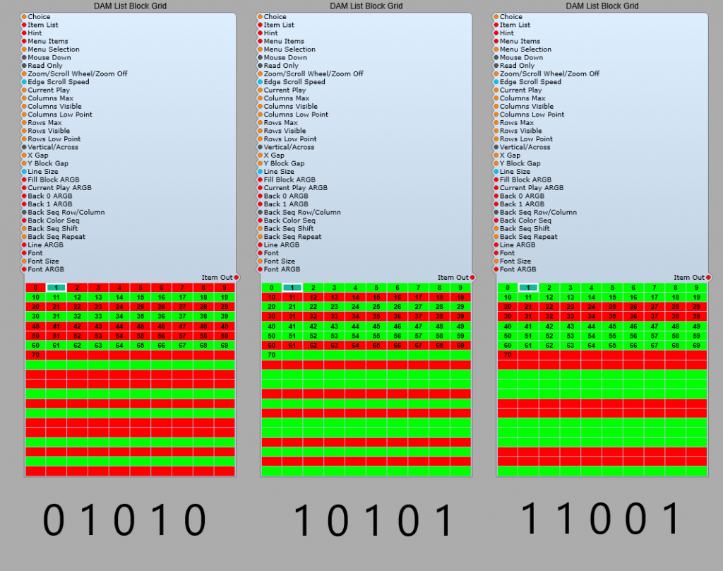
I took a while for me to understand how this sequencing works, one way to do this is with three of the modules set up identically (no need to connect to anything else) as shown below

Demo sequence:
Set Columns Max to 10
Set Columns Visible to 10
Set Rows Max to 20
Set Rows Visible to 20
Set Back 0 ARGB to FFFF0000 (Red)
Set Back 1 ARGB to FF00FF00 (Green)
Now set the Back Color Seq as exactly shown below each module.
Set Back Seq Shift to 0
Set Back Seq Repeat to 5.
You should see the same as I have shown below.
Note: You will find that if you have a 0 at the start of the sequence and a 0 at the end of the sequence (i.e. 0 1 0 1 0) then your colours will start as red green red green red green…so far as expected but at the end we then get a red followed by red, what’s going on? Is this right? well yes it is. If you think about it like below

Sequence 1 Sequence 2

So, If you want to avoid the doubled up colours at the end of the sequence, make it an even number of steps in the sequence. (0 1 0 1 0 1), just make sure you set Seq Repeat to 6. Always have the Seq Repeat value equal to the number of steps in your sequence.

Sequence 1 Sequence 2
RGRGRG RGRGRG
010101 010101

12 Stage stereo phaser.

Creating a multi stage Stereo Phaser with a Resonator.

You’ll need third party modules for this project.
I used these modules created by Davidson;
DAM List Block Grid
DAM V Knob
These modules by Elena Novaretti;
ED GUI Divide (Float)
ED GUI Add (Float)
ED GUI Line 3
ED GUI Fixed Value (Float)
This TD Module;
TD SV24B (You could use the Stock SV Filter, but I don’t think it sounds quite the same)
This QTN Module;
QTN VoltToGUI (Float)

Left and Right Phaser container.

Multi-Stage All-Pass filter

This although looking complex is actually twelve All Pass Filter modules in series, with the outputs of modules 2, 4, 6, 8, 10, and 12 connected to a Switch (Many > 1) allowing the selection of how many filters are in the chain. The control voltages are used on all the Filters, and only the first All Pass Filter is routed to the input IO module.

Stage Selector.

Here I have used a 3rd party module, Davidson’s DAM List Block Grid (you could substitute the stock list entry module but I personally think this looks better.
It’s connected to the PatchMemory List3 module to convert to the green list plug.
As with any list all the values will be automatically read from the module it’s connected to.
Settings.
The only settings I have changed on the Block List grid are;
Columns Max = 6,
Columns Visible = 6,
Rows Max = 1,
Rows Visible = 1.
To adjust the height and width of the Block Grid, open the panel view, select the grid and drag the borders to the required size.
Note: I will be doing a separate post on all the features and settings of this module in the near future.

The DAM List Block grid is also used in the same manner for the +ve/-ve audio switch, just change the columns to 2, and the rows to 1.

The control knobs.

This is another one of Davidsons 3rd party modules. This one has the advantage that it can be customized, and even better resized unlike the stock Knob control.
As with the stock Image2 module when using it for a control knob, the Animation position is fed through a PatchMemory Float3, and a Float to Volts module to provide the DSP voltage output. As per usual the range of the control is set from the Min/Max setting of the PatchMemory
Settings.
The only settings I have changed on the DAM V Knob are;
Radius = 70 This can be adjusted to suit your GUI. It controls the total radius of the control knob,
Back Line Top ARGB = FF880000 This is the colour of the line on the outer rim of the control that follows the needle,
Start/End position = 30 as this makes the knob behave more like a traditional control knob. This controls the start and end positions of the controls rotation,
Number Display (In the module properties panel drop down list) Change this to “Number Text”
Font ARGB = FF000000 you can change this to your own choice of colour, this is the number displayed in the centre of the control.
Needle ARGB = FF880000 to match the Back Line colour.
Needle Size = 0.6

Note: I will be doing a separate post on all the features and settings of DAM V Knob module in the near future.

Resonator.

The resonator is a TD_SV24_B filter module set to BP 12 module. There is a Level Adj module on the Res 0-10 input with it’s Input 2 plug set to a value of 9V so that the filter stays just below the point of self-oscillation. The filter type is set to BP12.
The Level Adj module in the output controls the amount of signal from the Resonator reaching the output mix.

Phase Indicator.

This is linked to the outputs of the Left and Right LFO outputs to give a visual indication of the phase difference between the two outputs.
This relies completely on third party modules.
The QTN_Volt2GUIFloat take the DSP input voltage and convert it to GUI Float, which is then fed into the ED GUI Divide (Float) module where we divide by 10 (Put a value of 10 on Input 2), and add 0.5 on Input 2 of the ED GUI Add (Float) module where it is then fed to the ED Line 3 module. I changed the thickness setting to 5, and the Line and Background ARGB settings to give red and green for the two channels, on a dark grey background

The complete Phaser

The LFO is a TD_LFO__ST with Phase control on the Right channel, and the LFO Type set to TriSaw. A good range for the LFO Hz control is 0.01 to 5.

The Phaser control panel

Tempo synced Echo.

How to sync an echo plug in with your DAW.

It’s often very nice to be able to synchronize an echo delay time to the song tempos in your DAW, you can get some nice rhythmic effects like this.

Getting the BPM from your DAW.

This prefab will allow you to enter the echo delay time in beats rather than in milliseconds. Sorry but we need some basic math to do this:
The BPM Clock2 module provides the DAW tempo in volts. It’s a direct relationship 60 BPM = 60 V, 120 BPM = 120 V and so on.
As we already know one minute = sixty seconds,
so we need to divide 60 by the tempo (voltage) in BPM to get the voltage required for one beat (This is provided our delay module is set up correctly) Setting up the delay comes later in this page.
Now, for instance if we have 120 BPM: 60/120 = 0.5, therefore a beat is 500
milliseconds long. Now what if you want to synchronize your delay to
halves or quarters rather than whole beats? All that’s needed is to set up another divider which divides the the beat’s length by 2, 4, and so on to arrive at 250, 125, or another step converted to milliseconds for your delay. The structure for this part of the Echo is shown below. Our fixed voltages are 1, 2, 4, 8 and so on.
Note: When in SynthEdit this will only run at the default tempo of 120BPM.

Delay modules.

The delay section is quite simple, all that’s needed is our two delay modules in a container. Make sure you have the Delay Time set at 1 second in the properties panel.

The complete BPM Synchronized echo is shown below.

This is good so far, but if you want to have an external feedback loop so you can introduce filtering etc. in to the loop, then because of the (unavoidable) latency in the Feedback Volts module the timings will go astray a bit causing some unwanted comb filtering effects.

Time correction in external feedback loops.

Fortunately there’s a handy output plug on the Feedback-Volts module the Delay Time Out, we just need to convert this from Float to Volts and apply the correction voltage to the Delay 2 modules, this will then alter the timing of the delay slightly to compensate for the Feedback Volts latency so that the feedback and the original signal can remain in sync.

DAM Kinetic Engine LTE.

About the DAM Kinetic Engine LTE.

This is a module for using a kinetic motion emulator to produce two varying control voltages, similar to the KAOSS bad on Korg KAOSS synthesizers.
The basic idea is of using a ball rolling on a surface, the shape of which can be controlled. The shape of the surface has either a positive hump (hill), or a negative hump (depression) which will affect the motion of the ball. The ball can be started with a trigger button, a clock pulse, or by triggering from a MIDI input.
Note: Using a MIDI trigger makes the module Polyphonic unless a Polyphony module is used to make the structure Monophonic.

The Kinetic Engine module and its plugs.

Left Hand Side Plugs:
Force Trigger:- This triggers a new throw of the Kinetic motion ball. Can be connected to the Trigger out of a MIDI-CV 2 module, or to momentary button. When connected to the MIDI-CV 2 module the module is Polyphonic, and will create a new ball for each note played.
Reset:- Resets the module to it’s current control settings.
Origin Start/Last:- Select whether the Ball is thrown from it’s current position, or from the position set by the Start X and Start Y controls.
Start X:– Value 0 to 1 V. Sets the start position of the ball, 0 being the Left Hand border of the surface, and 1 the Right Hand border.
Start Y:– Value 0 to 1 V. Sets the start position of the ball, 0 being the bottom border of the surface, and 1 the top border.
Direction:– Value 0 to 10 V. Sets the direction in which the ball if pushed along the surface.
Force:- How hard the ball is pushed in the direction of travel.
Slant X:- Value 0 to 10V. Tilts the plane of the surface on the X axis.
Slant Y:- Value 0 to 10V. Tilts the plane of the surface on the Y axis.
Surface Friction:- Value 0 to 10VCoefficient of Friction of the surface (how much it slows the ball down over time).
Time:- Value 0 to 10V. Slow down or speed up time (the rate at which everything interacts).
Lag:- Value 0 to 10V. Controls how “sharply” the ball bounces off a boundary. The more lag the more the ball curves.
Contour Shape:- -10 V to 10V. Controls the slope of the “hump” from the edges to the centre point. Negative values are a dip, and positive are a peak. Some contour examples are;
1) Gravity- The closer to the centre the greater the attraction or repulsion,
2) Linear- Constant slope,
3) Shallow- Steep at the edges and gentle in the centre,
4) Steep- Gentle until the ball reaches the centre where the slope markedly increases. There are more shapes to try, experimentation is the key.
Contour Pos Snap:-
Contour Height:- Value -10 to +10 V. Controls the height of the hump, or depth of the depression.
Contour Pos X:- Value -1 to +1. Position of the Hump/Depression on the X axis.
Contour Pos Y:- Value -1 to +1. Position of the Hump/Depression on the Y axis.
Boundary Thru Off/On:- Turns on and off the boundary (walls) when on the ball bounces off the wall, when off the ball wraps to the opposite boundary.
Note: All the parameters are designed to be voltage modulated from an LFO or random voltage source, but do remember the parameter ranges.

Right hand side plugs:
X Pos:- Range 0 to 1 Volt. The output control voltage relative to the position of the ball on the X axis.
Y Pos:- Range 0 to 1 Volt. The output control voltage relative to the position of the ball on the Y axis.

Using the Module.

This makes an ideal way to demo the module and get a feel for how it reacts to the various settings and the various contours.
IMPORTANT NOTE: Make sure all the containers used have their properties set to “Visible”, and “Controls on Module” for the Structure/Prefab to work Correctly.

The Volts 2 GUI Float prefab.

Nothing special about the converters for the “Bump” X and Y position converters.

Kinetics Display.

This consists of a DAM Poly Capture XYZ, and a DAM Poly Render to convert the X and Y voltages to the display format. A DAM Rectangle is used to add a border representing the boundary, and a visual representation of the “hump” in the surface and its position. The ED GUI Multiply float modules are used to correctly scale the Radial Circle values for display. (As shown added to the module names in brackets i.e. (300)).
Note: the following settings in properties are required. Make sure that the radial circle is ON, and the Radial Circle Bottom is set to 00 (Transparent). Set the outline to ON, and to your chosen colour.

Set the Top and Bottom ARGB for your required background colour for the Kinetics pad.

The complete Kinetics display structure is shown below. Position Z sets the size of the ring around the Kinetics Ball.

Switching the “Bump” colour.

With this String switch prefab we can change the “bump” from white (positive values), to black (negative values). The comparator switches between high, and low, which sends a 0 or 1 to the switch to change the Radial Circle Top colour from Black to White as required.
It actually switches at 0.001 V (1mV) which is close enough to make little difference.

The finished Kinetic Engine prefab in action.